- Home
- Logic Level Converter

Logic Level Converter
Replacement:BOB-11978. We've released a new rev of this Logic Level Converter that fixes the issue with the board not stepping down from 5V to 3.3V correctly. Go check it out! This page is for reference only.
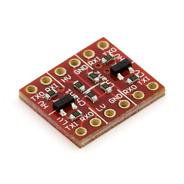
If you've ever tried to connect a 3.3V device to a 5V system, you know what a challenge it can be. The SparkFun logic level converter is a small device that safely steps down 5V signals to 3.3V and steps up 3.3V to 5V. This level converter also works with 2.8V and 1.8V devices. Each level converter has the capability of converting 4 pins on the high side to 4 pins on the low side. Two inputs and two outputs are provided for each side.
Bread board friendly! Can be used with normal serial, I2C, SPI, and any other digital signal. Does not work with an analog signal.
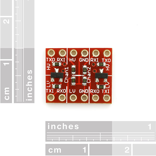
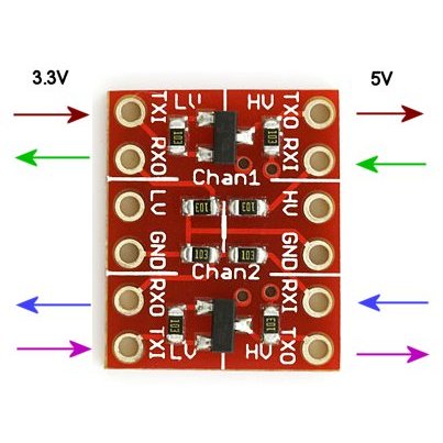
The level converter is very easy to use. The board needs to be powered from the two voltages sources (high voltage and low voltage) that your system is using. High voltage (5V for example) to the 'HV' pin, low voltage (2.8V for example) to 'LV', and ground from the system to the 'GND' pin.
Pins are labeled as Inputs and Outputs. These are relative to the board. A digital one going into the RXI pin on the 5V side will show up on the RXO pin on the 3.3V side as 3.3V. A digital one going into the TXI pin on the 3.3V side will show up on the TXO pin on the 5V side as 5V.
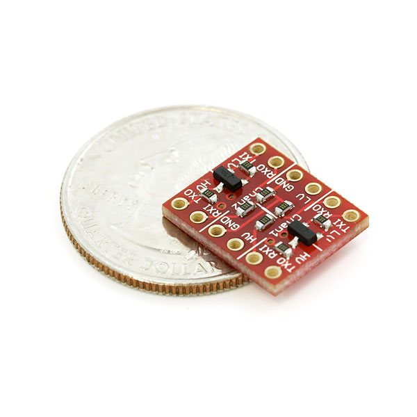
- 0.5x0.6"
Logic Level Converter Product Help and Resources
Core Skill: Soldering
This skill defines how difficult the soldering is on a particular product. It might be a couple simple solder joints, or require special reflow tools.
Skill Level: Rookie - The number of pins increases, and you will have to determine polarity of components and some of the components might be a bit trickier or close together. You might need solder wick or flux.
See all skill levels
Core Skill: Electrical Prototyping
If it requires power, you need to know how much, what all the pins do, and how to hook it up. You may need to reference datasheets, schematics, and know the ins and outs of electronics.
Skill Level: Rookie - You may be required to know a bit more about the component, such as orientation, or how to hook it up, in addition to power requirements. You will need to understand polarized components.
See all skill levels
Comments
Looking for answers to technical questions?
We welcome your comments and suggestions below. However, if you are looking for solutions to technical questions please see our Technical Assistance page.
Customer Reviews
No reviews yet.
While I am a novice, I am learning & appreciate feedback if what I am writing is incorrect.
1. The Tx lines are bidirectional. HUGE selling point & important for people using protocols like I2C. The Rx lines are unidirectional; only 5 to 3.3v
2. The Rx lines are not designed well for two reasons:
a) The resistors to generate a 3.3v output low side should be 10k R1 and ~20k R2. As is, the two 10k resistors split the voltage 50% resulting in approx 2.5v low side. This is outside the acceptable window for many 3.3v part like the LIS302DL sold on this site.
b) The two grounds on the breakout are common to each other. If the two ground were NOT common, then a user likely myself could be another resistor in series with the R2 on the breakout to adjust the low output voltage on each channel. Since however, they are common this is not easily possible because now current can flow between channels between the internal R2 and an external R2 in series.
I recommend posting portions of all the above for the benefit of your customers. And consider 2 for a future rev of the breakout.
SFE should make a version with four tx lines...
thanks for the explanation.. this is exactly whats going on.. i was wondering about the 50% split on RX the lines myself..
and just to clarify - you can use one I2C device with one of these.. both, SDA and SCL lines have to be wired up using the two TX lines of this board..
If controlling an i2c device from 5v, you can use a tx line for sda and an rx line for scl. You must use both TXes for a 3.3v i2c controller and a 5v peripheral
About the voltage divider, doesn't the RXO voltage depend on the current? The RX output of 2.5 V is correct only if the current is zero. Suppose there is a current as low as 0.16 mA (toward to the ground), the voltage will become 3.3 V.
Are we under assumption that the current in the RXO are so low that it is negligible?
You are correct that the output of the voltage divider does depend on current. However, higher current draw will decrease the output of the voltage divider: 0.16 mA of current will result in 0.33 mA of current through R1 and 0.17 mA of current through R5, resulting in 3.3v drop across R1 and an output voltage of 1.7v. Most microprocessors have very high impedance inputs, so current draw will be negligible, but you should check the documentation for your part to be sure.
Being that this post was 4 years old and there's talk of new boards, I figured this comment didn't apply any more.
WRONG!
I'm getting 2.5v on the RX0, which is unacceptable for my purposes. This is clearly contradictory to the diagram showing 5v in and 3.3v out, both on Tx and Rx lines, and I'm feeling a bit gypped.
I realize that this is far removed in time from the original post, but I thought I might add a note for users with similar issues:
A relatively painless option for changing the resistor divider in question, regardless of which board revision you have, is to add resistors either in parallel with the either the 'top' resistor (from RX_HV to RX_LV) or 'bottom' resistor (from RX_LV to GND), (off of the break-out board). This approach effectively lowers the resistance of either the 'top' or 'bottom' resistor, shifting the output voltage up or down respectively.
(http://en.wikipedia.org/wiki/Resistor#Series_and_parallel_resistors)
A similar approach could be used to 'speed up' the 'pull-up' on the TX side(s) with either of the the pull-up resistors, or using a similar suggestion to (b) above the pull-ups on the TX lines could be 'slowed'.
Somebody should second check me on this but I think the board I just got corrected this. The RX lines now seem to have 10k and 20k resistors so they level shift appropriately. It would make sense as I'm positive this is a new batch of boards.
Works great, But Really small and easy to lose! (But that's just me)
Hi, and thanks for all the good work.
One question on this logic level converter:
If I want to use this to connect a 5V processor to a 3.3V I2C sensor, can I connect one pin of the processor to the SDA pin of the sensor with both a TXI-TXO and a RXO-RXI line in parallel, and then switch that processor pin from input to ouput as required?
If not, what do you recommend I do?
I think you can do that with this board. You'll need to use the two "TX" channels, (the ones with the MOSFETs), since I2C requires bidirectional I/O for both lines. There is a good appnote on the subject here.
Read this appnote. Print the schematic and compare to the BOB schematic. All will make sense! Thanks for the reference Quazar. Gotta get some of these on order as my chipKIT Uno is a 3.3v device.
Thanks for sharing the app note here. It really helped in understanding the concept behind logic converter.
I'd love to see a Ti TXS0104/108 breakout variant of this board...
This board is a great example of why SparkFun just "gets it." You just know they've come across this problem themselves, got frustrated with having to solve it multiple times, and came up with a solution. Rock on, guys!
Why not just make a breakout board for the TI TXB0108 and/or TXS0108E? 8 Bidirectional level shifting lines, and the chips are only $2 each.
What he said. I just used a TXB0104 on a project to connect a 3.3V mbed to some 5V devices, and it worked great. Each channel can be used for either input or output - it figures out the correct behavior on the fly.
The chip isn't available as a DIP though, so having one on a breakout board for prototyping would be great.
Those don't work with i2c though
The example table in the breakout schematic has a column LV. This leads the reads to believe that LV has some affect on the Max output. It doesn't. Its not even connected to the circuit. I recommend removing that column for clarity.
For clarity yes it is.... Look at the underside of the board.
Can this be used as a 24v to 5V converter?
Using it for I2C
I connected mine the same way this page shows: example
But I still get random crashes. I am using it with the MD25 motor controller and the 9dof sensor stick (SEN-10183). Seems like the Arduino shouldn't be crashing even if there is junk on the I2C line. It should reject it or give bad data, not crash. I have 1k ohm pull ups on both sides of the converter. Any advice would be appreciated, thanks.
I'll have to second a few other comments here: the 10k/10k divider on the RX lines had me pulling my hair out for a little while with a touchy SD card (one card worked, even though 2.5V was out of spec, but another card didn't). Suggestion for a future revision: use FETs for all four lanes. Now, you've got a four-port bi-directional level shifter.
Good example (but skip the voltage regulator):
* http://www.rocketnumbernine.com/2009/04/10/5v-33v-bidirectional-level-converter/
* http://www.rocketnumbernine.com/2009/06/13/bidirectional-level-converter-pcb/
Yes! Definitely needs 4 FETS.
I had a miserable time with this thing because the voltage divider line may only work with devices that do not have RX lines pulled up!
Works great with the BOB-00199 and a DB-25 for a USB to Serial break out box.
The DB-25 alowed me access to all BOB-00199 and BOB-08745 ports.
I now have Lo/Hi voltage TTL, GPIO's, serial, reset/suspend and 3.3v/5v all on the DB-25 jack.
You wont find a USB to RS-232 converter in any big box store that can give this kind of flexibility.
I would have liked two through holes (redundant) for each connection.
This would give a little bit more flexibility in some situations.
Not a big deal and most of the time this wouldn't be needed, just nice to have...
There seems to be enough question around the subject, since the tool is used mostly for I2C and UART, how about a simple couple of schematics showing the I2C connection where the bi-directional lines must be used along with another showing a connection between two UARTS (on microprocessors) and finally between a 3.3v microcontroller and teh RS232 interface to a PC/USB?
Can I assume that the board has to be viewed from the perspective of the low voltage side of the interface you are trying to make? So the TXI will hit the 3.3v TX pin while the TXO will hit the RX pin on the 5v device? Sorry for not being bright enough to figure that out on my own.
If you're working with up above about 1MHz clocks, watch out for those resistor dividers. They'll attenuate your signal.
Great! I bought 10 of these and now they're no good. Thanks for the notice. Wayne Bjorken
Not sure if this is a known problem. Can anyone please suggest? 1. I connect the Arduino UNO R3 SCL pin to HV_RX1. Measure voltage wrt to GND (Arduino Pin) and get 5V 2. As soon as I connect the Arduino GND to LLC GND, the voltage drops to 1.7V. Eventually, on the LV_RXO, I get 0.8V.
Am I missing something? The LLC is now soldered and I can’t even return. Grrrrrrrrr
I have a few of these, and see now that they have been replaced by a newer product. Should I be concerned with using them in a project, as the new one says something to the effect of, the old model had problems. I don't want to fry anyhting.
You don't really have to be concerned about frying anything. The problem is in the voltage divider setup (two 10kOhm resistor divider). With the revision on this page, a 5V input level may actually result in a 2.5V output level. For some 3.3V devices, this is lower than they would like (datasheets may include data on what the minimum 'high' voltage state for a given pin is) and they read it as an indeterminate state, rather than a high. ( You'd be okay for low. )
There is a comment further up noting that their board did have the correct voltage divider setup - one 10kOhm, one 20kOhm, as in the new revision - a long time ago, so there's even a chance your boards don't have this issue at all. Suffice it to say that if the application you have been using them in is working fine, it'll probably keep working fine, and any others you'd build with the same components (beware batch differences) should be fine as well.
If you're seeing iffy behavior, on the other hand, consider some of the solutions provided in other comments (e.g. add a resistor to make a 10kOhm and 5kOhm divider, or replace the resistor in err entirely), or look into the new revision :)
Hate to knock your board, but for a bit more, this one has some nice features.
http://www.adafruit.com/products/395
THanks for the feedback! This is actually designed to be the cheap and simple solution, but you are correct that there are plenty of other options with many more features. This is the most basic K.I.S.S. ( keep it simple solution).
Probably a dumb question but here goes... If I've made a shield using this kind of logic level converter to go form 5v on an arduino to 3.3v, what happens if I put it into a 3.3V arduino so that it is now going from 3.3V to 3.3V? Will it still function or just stop working?
Does it works to connect a 24V signal to a 3.3V µC ?
Works like a charm. I soldered a row of header pins on each side to make it stick into a bread board. Be warned that it is one row to wide to bridge the center like it should, but it still works just fine.
I m having problem using level converter and because of that my rn xv module is not communicating with microcontroller correctly what i should do to communicate correctly ???
I made an instructable on how to use this to connect an Arduino and a Beaglebone or rPI or any other ttl serial system http://www.instructables.com/id/How-to-make-a-BeagleBone-and-an-Arduino-communicat/
I am a noob trying to connect the raspberry pi i2c to the arduino uno so as to do the master slave configuration. This may have been asked before but there are 107 comments so sorting would take a long time. Is there a schematic that I can reference for this application.
I just posted this today and it includes i2c between beaglebone and arduino, lucky you! http://www.instructables.com/id/Environmental-Monitoring-with-BeagleBone-or-Raspbe/ I'm not sure on the rPi if you can connect them direct like that though, but i think data on TX and clock on RX should work.
I would really appreciate someone's assistance for a quick question. I am confused by the description for this item, it says, the board needs to be powered from the two voltage sources.
I have a 3 volt circuit on one wire. At this time, it count on 1.5 volts or higher.
Would this item help me bring the voltage above 2 volts on a positive count? Should I use another item to accomplish this,..
I am trying to interface the MPR121 with 5v 8051 micro controller. I have also purchased the logic level converter. Should i used pull up resistors for the IRQ pin even if i use a logic level converter ?
I can't figure out how to work this properly. I am running an arduino due arduino mega serial communication. When i send through the TXI TXO 3.3V to 5V everything works great. Now when I send 5V to 3.3V on TXI TXO everything looks great on my oscilloscope as long as I do not plug in the TXO to my RX pin on the 3.3v DUE. As soon as I plug in the RX the oscilloscope reading plumits from a 3.3v signal to a 1.3v signal (which is uselss). I have tried using pullup resistors on both sides (Which cleaned up the signal rise time a bit with the oscilloscope attached only) but I still get only 1.3v. How do I get this thing working!
The 5V system that I have with open-collectors (a commodore 64) does not have a fixed 5V on the specific port (IEC) that I am going to connect to my 3.3V system (Raspberry Pi).
The Pi however, DOES have both 3.3v and 5v fixed. Would it be possible to use the fixed 5V from the Pi on the HV pin on this board, as long as I connect both grounds from the Pi?
See, I'd rather not take the 5V from a different port on the 5V system, since it would be a little messy with the wiring.
I have a 3.3V PWM signal I need to boost to 5V for an RC servo. This board looks like it'll do it, but just want to double check.
hi I'm doing a weather station with mega freeduino. I turned off the internal pullup freeduino and enter them in the following as hardware sensors that make up the project: 1. RTC clock that keeps the time in UTC, it works with 5V. 2. BMP085 barometric pressure, operates at 3.3V. 3. DHT22 for the temperature and relative humidity. to work best on the I2C RTC and the BMP085 I applied a cenvertitore logic level of SparkFun, so I used the 2 lines TX for SCL and SDA. I put the resistors on the lines of the SparkFun TX? because I have the RTC is slowed or flag as TIME string 165,165,165 and so on. alone works fine. how can I fix this error likely I think that depends on the converter? where should I put any further resistance?.
Somehow, this component is dragging my entire 3.3V bus up to 5V. Here’s the setup:
I’m only using one TX channel. The high side is 5V, and the low side is 3.3V. I bring the reset pin from an Arduino into the TXO channel on the high side (it should be held at 5V except to reset). I haven’t yet connected the TXI on the low side to anything. When I power on, my 3.3V bus is brought up to 5V! I’ve tested for a short; there is none. If I remove the component, my 3.3V bus is in fact 3.3V. Further, if I tie the TXI on the low side to ground via a 1kOhm resistor, I find that my 3.3V bus returns to 3.3V. I’ve also tested all of my connections; they’re good.
Does anyone have any idea what’s going on? Leakage current? Directionality?
It wasn't this component's fault. It was the 3.3V line connected to the AREF pin of the Arduino. I didn't have the AREF pin set to EXTERNAL in the sketch, and so it was at 5V by default and actually driving my 3.3V bus up to 5V. The problem didn't occur until I ran a sketch that required this level converter, thus implicating the level converter, but the level converter is innocent.
This is a great little level converter. I'd pay twice the cost to have MOSFETs on the RX channels too. There's are also plenty of level shifter components that can handle many more channels; I would definitely pay for one of those on a breakout!
The MOSFETs on this chip are rated 50V max. Can this handle a 12V - 3.3V conversion? I could do the math, but I bet someone already knows the answer :D
It would likely work through the MOSFETs in the low to high direction, but note that the high to low direction relies on a 50% voltage divider, which would result in 6V out. Ouch.
Well, I'm going to comment on this product. Generally it is great to have and I'm using it on several circuits. I have found that, when using the RX lines (since they are simple voltage dividers) that in a few (not very often) situations, the shifted voltage does not work correctly for the low voltage receiving device. I have been agonizing over why serial data from a GPS chip is not seen by an ARM processor's UART. I finally switched over to use the TX (really bi-directional) line and now the data is coming through. If Sparkfun has the opportunity, though it may up the cost of this cute board a little bit, but I would suggest they use the MOSFET circuit's on both data directions for more accurate level shifting.
Just got my Arduino Due and was looking for a good multi-channel logic converter. My math tells me the voltage divider should be something like 10k and 15k for a 5v -> 3.3333v conversion. Am I missing something here? The data sheet still says 10k -> 10k. I realize it is less than 2 bucks, but I do already have the parts on hand. Was just trying to make life a bit easier.
Does this now function as it is intended? (A 5v to 3.3v converter.)
Thanks, Jeremy
Does this work good with 115200 BaudRate?
Could it be used with raspberry Pi for protecting the gpio pins from high voltage? interfacing gpio with relays and other high voltage stuff.
Depends on what you consider high voltage. You can use this board up 5 volts (Per the Description above). I have used in the past Sparkfun's Optoisolator Breakout BOB-09118 for true protection.
Ok I successfully connected a 3.3v I2C sensor to Arduino 5v using only 1 TX for the I2C protocol (SDA), can anyone tell me why on earth does the clock need to be bidirectional ? I read in all the comments that both I2C lines should be connected to the TX, but since the RX are only 1 direction to the LV, it blocks any other input signal i needed from the sensor. Since i connected it to the MPR121 touch sensor i need an interrupt input from the sensor which is actively high, so i connected it to the TX, and the SCL to the RX. The sensor is working perfectly, can anyone explain why the SCL needs to be bidirectional, when does the I2C slave input a clock signal ? Thanks and if anyone wants into on how to connect it to the MP121 Touch sensor write me id be glad to help.
When reading from an I2C slave, if the slave does not have data ready fast enough for the master, it utilizes something called "clock stretching", where the slave holds the clock low until it's ready.
Thanks, I am using this for the MPU6050 acellerometer to play it safe (some people say it can interface with 5v arduino fine, because of some weird reason, but it's supposed to be 3.3v) Anyway, I'll be trying your method because it sounds to me like it should work. (I need SDA, SCL, and 1 interrupt.)
http://ics.nxp.com/support/documents/interface/pdf/an97055.pdf is some good information on bidirectional level shifters. I would not use a resistor network to step my signal down.
I just used this in a project to connect up a 3.3v magnetometer and a 3.3v accelerometer over I2C/TWI to a 5v Arduino Leonardo (Also worked with an Uno). The two I2C wires on the arduino connect to the "TXO" lines, HV connected to 5v, LV connected to 3.3v, both GND wires grounded, and the two "TXI" pins connected to the magnetometer and accelerometer being sure to match SDA and SCL lines, and I used a 4.7k pull up resistor on each line. Very simple circuit, and works PERFECTLY! No need to connect anything to RXO or RXI pins.
So if I wanted to hook up a 5v signal (Arduino) to a 3.3v device (gyroscope) exactly which connections would I make, where does the 5V go in and the 3.3v come out? Are the ground connections in the middle common? Thanks alot, will be buying a few of these!
Wouldnt 10k and 5k be a better voltage divider on the RX lines, instead of 10 K and 10K? In the schematic is a table that shows the relative values of the output for the RX lines. What about the output on the TX lines coming through the MOSFETs? Are they the same as the out voltage?
Bought one. Works brilliantly. Used it to connect 3v serial (TTL) to 5v serial on arduino uno. Works perfectly. I soldered on male headers so I could reuse it for other projects. (in fact I do that with everything now)
One suggestion for a future revision: redo the silkscreen to say "In" on one side, and "Out" on the other side, for each channel. Right now, both sides say the same thing. Makes it confusing to hook up. If one side says "In" and the other side says "Out", you easily know the direction it's going. Just a suggestion. Works fine as is but that would help other people wire it up first try.
How much current will this draw on the 3.3v "LV" pin if I use this module for serial communication? Will it draw more than 5mA?
What is the product id for that transistor on Sparkfun's product list? I searched but could not find it. It's called BSS138 or as the product's datasheet also calls it "N-Channel Logic Level Enhancement Mode Field Effect Transistor". Is there maybe a non SMD equivalent on this site that I could rather use on my breadboard?
I'm a novice and experimenting with this using just an Arduino before hopefully using it to connect my Arduino to my Raspberry Pi. When I connect 5v to RXI I measure 1.5v at RXO rather than the expected 3.3v. I still measure the 1.5V at RXO even if I don't connect 3.3v to LV. I have the Arduino 5v connected to HV, Arduino 3.3v to LV, both GND to Arduino Ground, and one of the Arduino digital pins connected to RXI that I'm setting High/Low in the sketch. I'm using a multimeter to measure the voltage between RXO and the Arduino ground. Could I have damaged the board by using it incorrectly or maybe I've soldered it badly? Thanks for any help or suggestions.
nevermind!
Hi, Is this board working well with an iPod/iPad in one or both directions?
Thank you.
i have a texes instrument microcrontroller (TMS320F28335) which runs at 3.3v and LCD module I2c which runs at 5v. i have a question, do i need to used pull up resistors in both sides of the converter? (2 resistors for sda and scl for low side and other two resistors for high side)
regards, david
David - Yes, you will need 10K pull ups on both sides of the converter. Have you looked at the NXP PCA9517A to convert the I2C bus from MSP430 to 5v I2C. Easy package to implement I2C at any voltage.
Member #34624 is right on. The operation of this circuit has nothing to do with a voltage divider to maintain the voltages.
It has to do with the gate on the MOSFET being held at 3.3V, so that current will only flow to "top up" the voltage in the low side if the voltage on the low side is anything less than 3.3V. With some small leakage to ground the voltage on the low side will stay at 3.3 unless the I2C device pulls that side to ground (transmit from I2C device), or the voltage on the high side falls to ground (transmit from microcontroller).
I've made my own version of these, but heck, these are cheap enough and look prettier than what I can make, so I'll get some.
Here is the original document from 1997 that explains the bi-directional function of the MOSFETs:
http://ics.nxp.com/support/documents/interface/pdf/an97055.pdf
(Google for an97055.pdf if it moves again).
2.3.1 Description of the level shift operation. For the level shift operation three states has to be considered:
• State 1. No device is pulling down the bus line and the bus line of the “Lower voltage” section is pulled up by its pull-up resistors Rp to 3.3 V. The gate and the source of the MOS-FET are both at 3.3 V, so its VGS is below the threshold voltage and the MOS-FET is not conducting. This allows that the bus line at the “Higher voltage” section is pulled up by its pull-up resistor Rp to 5V. So the bus lines of both sections are HIGH, but at a different voltage level.
• State 2. A 3.3 V device pulls down the bus line to a LOW level. The source of the MOS-FET becomes also LOW, while the gate stay at 3.3 V. The VGS rises above the threshold and the MOS-FET becomes conducting. Now the bus line of the “Higher voltage” section is also pulled down to a LOW level by the 3.3V device via the conducting MOS-FET. So the bus lines of both sections become LOW at the same voltage level.
State 3. A 5 V device pulls down the bus line to a LOW level. Via the drain-substrate diode of the MOS-FET the “Lower voltage” section is in first instance pulled down until VGS passes the threshold and the MOS-FET becomes conducting. Now the bus line of the “Lower voltage” section is further pulled down to a LOW level by the 5 V device via the conducting MOS-FET. So the bus lines of both sections become LOW at the same voltage level.
Note that the gate has to be connected to the lower voltage. Yes, they wrote MOSFET with a dash in 1997.
Why can't I just use a simple resistive voltage divider with 1.5k + 3k in series, take the output across the 3k resistor to get 3.3v?
That would be used on the TX line of the 5v device. Is it because the +3.3v on the other device's TX isn't a strong enough logic high for the +5v device's RX?
Often this will work fine. As you've guessed, the real issue is whether the 3.3V TX side's H and L levels will match up with the H and L thresholds of the 5V RX side. You can often determine this information from both datasheets, see this tutorial for info.
According to the ATmega328 datasheet, Vih is 0.6Vcc at Supply voltage of 5v.
So Vih in my case is 3v.
I'm probably not going to find a datasheet for an iPhone 3G (my 3.3v device) so i'll just have to try it and find out!
Thanks for your help :)
If I use this to connect a 3.3V device to a I2C bus, do I still need to insert pull-up resistors? I noticed that it has 10k pull up resistors on each side.
I'm connecting the HV side to my Arduino and as far as I know I'm supposed to connect 1.5k pull ups to 5V, do I need to?
What pull-up resistors would I need on the 3.3V side if any?
See I'm able to receive perfectly, but I can't request data. The onRequest ISR on the Arduino does not run. I want to know if this could be a problem at the physical layer. Also the 3.3V comes from the Arduino's regulator and not from the device's 3.3V regulator. As long as all the grounds are connected together it should be fine right?
Thanks
Good Stuff!
i want to use a 5v i2c motor driver with my 3.3v controller? how do i have to connect it without getting some kind of loop?
What are the specs on those resistors? I know they are 10K but what about the rest? I only need one channel and I'm building this myself (first little project). It looks a 0603 SMD resistor. Is it 5% 1/4W?
I was connecting a 3.3V Arduino Pro Mini to a 5V SRF05 Ultra-Sonic Ranger in Mode 2 (single pin for Trigger and Echo.) I could not get it to work for anything using TX_LV and TX_HV (plus HV, LV, and ground connected.) I think the pull-up resistors were the problem. Finally I tried using RX_LV and RX_HV (plus ground), and it worked just fine. I hope this will help someone else.
Thanks! This comment totally helped me, I can confirm what you described. Either we both misunderstood the description, or it is wrong.
Have to correct myself here. The RX lines seemed to work better, but where not sufficiently reliable in the end. Finally I realized that I needed to connect the ground on BOTH sides in order to get rid of the floating inputs. Did that and switched back to the TX lines, and everything works like a charm!
Hello!
I'd like to connect two arduinos (3.3v and 5v) by the serial connection. Will this logic level converter allow me to transfer data via serial interface?
If not - what is the best solution to link two arduino with different operation voltage?
Thanks.
hi can i use this for connecting arduino uno to linksys WRT54GL instead of MAX232??
Here's another usage of these really versatile boards:
https://trandi.wordpress.com/2011/09/26/vfd-clock-connects-to-the-internet/
Dan
Well I am wondering how to connect to get 5 volts this for example to a Lithium battery of 3,7v (like this one http://www.sparkfun.com/products/341 ). Because say something like "The board needs to be powered from the two voltages sources (high voltage and low voltage)", but I think this is the common case where we have a battery and single voltage source. Any suggestions?
This really isn't designed to handle that much current. I think what you're looking for is a buck/boost converter. Something like this: https://www.sparkfun.com/products/10255
Yay for shortcuts!
I wonder if Sparkfun ever thinks about making these a little bigger, with terminal blocks for easy screwing and unscrewing of wires? I know that it sounds silly for logic level voltages, but it would make attaching my sensors (already buried in the ground) to the level shifter a bit easier. Soldering in the field isn't very much fun...
Hi I Can confirm that using the sparkfun level converter works with the LSM303DLH on a Arduino Uno and stuff
https://picasaweb.google.com/lh/photo/AIiOfELj07YYfxNzte1jWfUyuJg5fbvJpQtmBljJuuk?feat=directlink
This version of the board has added circuitry to address concerns about voltage translation on the SDA and SCL pins.
Sparkfun posted this information here >> http://www.sparkfun.com/products/10703
I will add to the chorus of people looking for FETs in both directions. I've been trying to use this to pair an Arduino with the Sparkfun GM682 eval board. I couldn't get it to work until I used the TXO/TXI pins to send output signals from the Arduino to the eval board (in other words, HV to LV on TXO/TXI pins, opposite to what is shown in the product photos).
Definitely a great product - just needs improvement!
Really great product !
I've been using it in quite a few different projects, like here where I needed to interface the 9DOF IMU with a 5V Arduino:
http://trandi.wordpress.com/2011/01/03/razor-9dof-imu-i2c-to-arduino/
Thank you guys for a great product as usually !
dan
Can anyone tell me the dimensions for the row spacing and pin spacing for this device? I would like to attach it to our main circuit board with two rows of pin headers, but need to know the dimensions for the level converter board pin spacings and row spacing. Thanks for help in advance!
Also has anyone confirmed that the latest boards changed the resistors per one of the posts so that it will work for 5v to 3.3 v conversions?
Is this in the sparkfun eagle library? If so, can't find it.
I've been experiencing communication issues with this logic-level converter used with 16 bit SPI messages @ frequencies > 2MHz between a 3.3v micro-controller and a 5v chip.
What is the maximum speed achievable with this board?
The input capacitance of the FET used is 55pF max, 40pF typical, so perhaps the 10K resistor (time constant about 0.5 microsecond) is what's limiting around 2 MHz?
http://www.datasheetcatalog.org/datasheet/siemens/BSS138.pdf
The GNDs are common on both sides. Does this mean you can't have two seperate supplies on each side? Or, can you have 3v side seperate, but just using the 5v gnd? tia
Sparkfun: Nice board. You might want to consider putting a square solder pad on Pin #1 so that someone can tell which pins are #1.
Hi,
I want to convert 5V PWM output of one sensor to 3.3V PWM for interfacing with MSP430 ? Will it work ?
Thank you,
Vatsal
It should, just be sure to use the TX channels with the mosfets, in order to get your PWM highs to be exactly your LV.
Hello! Could someone explain what the HV and LV pins are for? I can't figure out any use other than for probing the input and output voltages for verification purposes. Shouldn't they simply be pulled to TXI and TXO voltages?
Also, I'm not sure how the mosfets do the voltage step-up. Can someone explain that as well? I would very much appreciate it - I'm fairly new to circuit design. Thanks!
The HV and LV pins are what cause the MOSFET to work. Essentially, the input signal controls how much current flows between HV and TXO. In order for the converter to work, LV needs to be connected to the logic high voltage (most likely vcc) of your lower voltage circuit, and the HV pin needs to be connected to the logic high voltage of your higher voltage circuit (also most likely that circuit's vcc)
I tried using one of these to convert from 5V (atmega8) to 3.3V (SD card). The SD card almost replied, but was giving back 7-bit "bytes". We think the problem was that the 2.5V "high" level wasn't high enough for the SD cards we tested with. Replacing the RX channels with 3:2 resistor ladders (instead of the 1:1 ladder included on this device) cleared up the problem.<br />
That means the only thing I ended up using from this device was a single TX channel, which would have been easier to do with discrete components.
Works perfectly. I used it to convert 3.3v TTL to 5v TTL to interface a GPS with my D90 camera. For those who are interested: http://www.flickr.com/photos/grink/sets/72157625472950584/with/5230195801/
Hi everyone<br />
I would like to convert sevral signal and clock from 5v to 2.5v is this board woul do the job.I mean the schematic show a split rqtio of 2.
The Schematic Document shows in the table that 5V -> 3.3V = 2.5V.<br />
Will this voltage be enough for interfacing an xBee with Arduino?<br />
For Level shifting on Rx and Tx lines.
udawatabhimanyu4,
Did you ever get your question answered. I'm about ready to test the samething.
No... I went on with the breakout Board for xBee. But then, if you have an Uno, then you dont even need any level shifting. It has 3v3 built-in!
Finally ordered some of these, and tested the first one today. This thing is great -- a real 3.3V 5V "Easy Button." One minor quibble is the pads could be made a bit larger for ease of soldering -- but I managed okay anyway. Definitely recommended.
I am using multiple 3.3v i2c devices(slaves) connected to an arduino(master). Do i need multiple level converters or can I put one level converter between the arduino and the devices?
Hi Elif,
The problem you're encountering, (though it's been a while so I bet you've figured it out already), is that the TX lines are pulled high, (through pull-up resistors on the board), anytime that nothing is acting to pull them low. Floating inputs will go high because of this, which is the intended behavior. Pulling the TX-line low on either side will cause the other side to properly transition to a low state.
Awesomeduck,
The device you refer to only passes the signal in one direction, from the 'A' side to the 'Y' side, so it wouldn't be useful to communicate information back the other way. Applying a signal to the 'Y' output side does not affect the state of the 'A' input associated with it.
Have a great day everyone!
~gorg0th
Having trouble. Trying to shift 1.8V signal to 5.0V.
Problem is, when I wire the 1.8V + GND and the 5.0V + GND, the TXI pins go high to 1.8V, and the TXO's go high to 5.0V, even though nothing is attached to the TXI pins (TXO's are attached to signal pin of NPN collecting from the 5.0V supply)
Any help would be appreciated.
My 5.0V supply is 1000mA,
and the 1.8V is ~ 150mA
this is the schematic of what i'm doing:
http://bit.ly/b4wghF
I seem to have the exact same problem. I wonder if anyone has experienced this also? help/explanation would be greatly appreciated!
EDIT: Nevermind. I should have scrolled down literally 1/4 page to gorg0th's explanation =)
How is this different than a 74LVC244 Buffer/Line Driver?
Hello ,
Can this be used to interface the GM862 uart (2.8V CMOS) with an msp430 uart (3.3V) ?
I bought two of these to convert levels between a 5v Arduino (arduimu) and a PNI micromag 3.
I did initially used the ports as suggested in the images above and it didn't work.
After some investigation, it turned out the level of signals from Arduino(5V) toward the micromag 93.3V) where at 2.5 instead of 3.3V.
I managed to get it to work by hijacking one of the TXO connections on Arduino side to convey the Reset signal. Other SPI signals (MOSI,SCK) where fine at 2.5V.
@Sparkfun, Would be good to highlight this in the Product info as already suggested above. If ever you build a new series of converter, might be good to tune the Voltage divider to effectively output 3.3v when supplied with 5V on the High side.
I'd really like to use this to Power a 3.3v circuit.
I'm guessing it will do that just fine, but is there some kinda current limit on this I should be aware of?
Everything on the page talks about communications but I really just care about power.
Would this work for that too?
This board has no provisions to provide any sort of power to a circuit. It is designated for communications purposes and in order to even do that it requires voltages to already be present in order to function. The parts on-board are mosfets not Voltage-regulators.
The description is inaccurate. It reads, "A digital one going into the RXI pin on the 5V side will show up on the RXO pin on the 3.3V side as 3.3V." In fact, a digital one going into the RXI pin on the 5V side will show up on the RXO pin on the 3.3V side as 2.5V.
So could I use this to boost the 3.3V digital out from an Arduino mini pro to 5V and then drive the TTL in on the SN754410 h-bridge?
Neat product.
Perhaps add a 3.3V regulator footprint. I am using the board between a LOCOSYS GPS unit and a 5V PIC and currently have two diodes to get about 3.8V from the 5V line - not ideal.