- Home
- Product Categories
- Wireless and IoT
- RF Link Transmitter - 315MHz

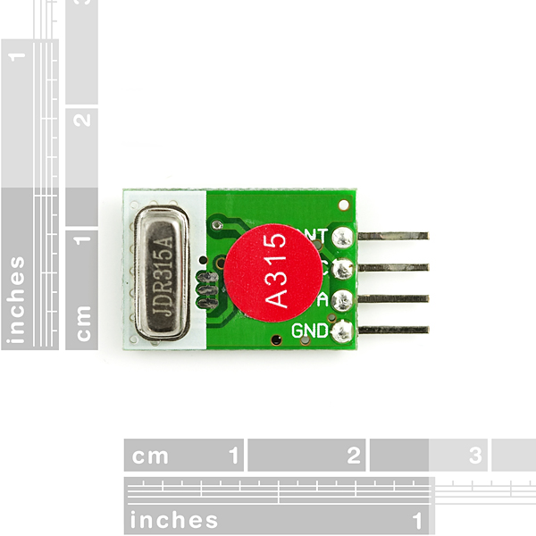
RF Link Transmitter - 315MHz
Replacement:WRL-10535. We are now carrying the same transmitter from a different supplier. This page is for reference only.
This is only the 315MHz transmitter. This will work with the RF Links at 315MHz at either baud rate. Only one 315MHz transmitter will work within the same location.
This wireless data is the easiest to use, lowest cost RF link we have ever seen! Use these components to transmit position data, temperature data, even current program register values wirelessly to the receiver. These modules have up to 500 ft range in open space. The transmitter operates from 2-12V. The higher the Voltage, the greater the range - see range test data in the documents section.
We have used these modules extensively and have been very impressed with their ease of use and direct interface to an MCU. The theory of operation is very simple. What the transmitter 'sees' on its data pin is what the receiver outputs on its data pin. If you can configure the UART module on a PIC, you have an instant wireless data connection. The typical range is 500ft for open area.
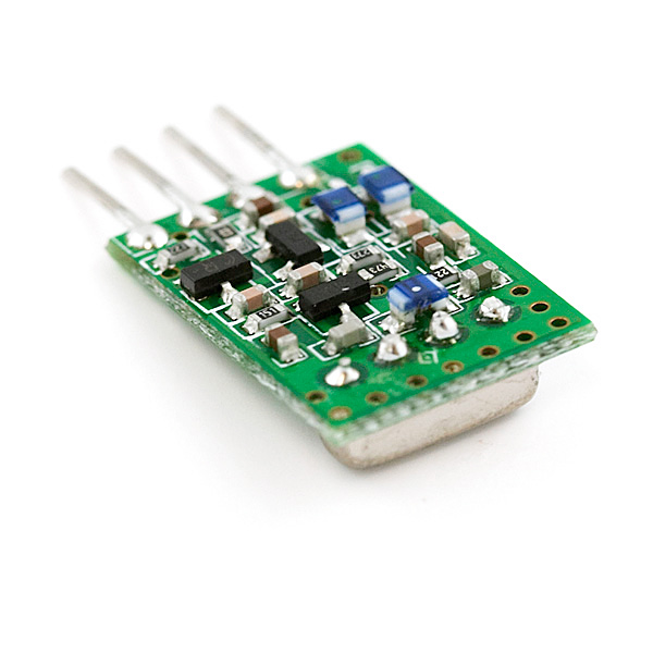
This is an ASK transmitter module with an output of up to 8mW depending on power supply voltage. The transmitter is based on SAW resonator and accepts digital inputs, can operate from 2 to 12 Volts-DC, and makes building RF enabled products very easy.
Supported Antennae: 30-35cm of wire
- 315 MHz Transmitter Operation
- 500 Ft. Range - Dependent on Transmitter Power Supply
- 2400 or 4800bps transfer rate
- Low cost
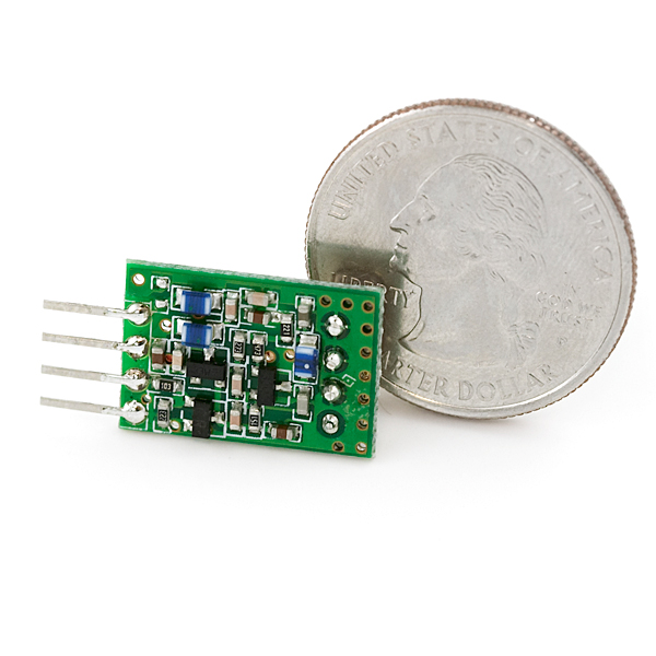
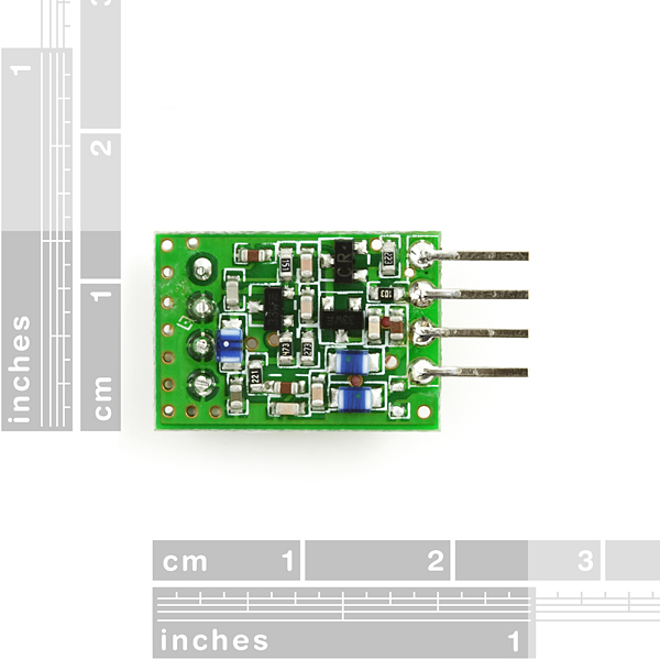
- Extremely small and light weight
Comments
Looking for answers to technical questions?
We welcome your comments and suggestions below. However, if you are looking for solutions to technical questions please see our Technical Assistance page.
Customer Reviews
No reviews yet.
I had difficulty getting correct/accurate data out of this chip. I stumbled upon this site and found it EXTREMELY useful. Now, 100% accurate data. I hated this transmitter until I found this site. Its for PICAXE but can be adapted
http://quicktrip.co.nz/jaqblog/index.php?option=com_idoblog&task=viewpost&id=25&Itemid=8
Not that it matters if there's no matching receiver, but I think this link has moved at some point in the past two years:
http://quicktrip.co.nz/jaqblog/home/25-rf-datalink-using-a-picaxe-uart
I got the 315mHz transmitter/receiver pairs to work without difficulty, running from and to PICAXE 08M and 14M microprocessors. I used 23.8cm straight wire antennas on each. I'm glad the 315mHz version is available--I tried 433mHz and found that I am totally swamped in that frequency. Apparently 433mHz is in or very close to a legal ham range in the U.S. which can transmit at hundreds of times the power.
The description is somewhat misleading when it says, "Only one 315MHz transmitter will work within the same location." Only one can work at the same instant, but for datalogging, with message transmissions of a small fraction of a second, many can work in the same space provided that you understand and work around the possiblility that collisions may occur with resulting data loss--so transmit multiple times with varying gaps between transmissions.
(disclaimer: I'm a licensed amateur radio operator) The 70cm amateur radio band is 420-450mhz in the US. It's unlikely to be an issue if you live out in the woods, but 70cm is a very popular band in cities. 433mhz is listed on the ARRL bandplan as used for repeater linking. You are wrong in thinking that hams can transmit at "hundreds of times the power" of this transmitter, though. Hams can transmit at 187,500 times the power of this transmitter. (Big Grin). I live in the Seattle area and would definitely select the 315mhz version.
Thanks for the information regarding "Only one 315MHz transmitter will work within the same location." I was not sure how to interpret that comment. And I want to prototype something that will require multiple transmitters!
You can use as many transmitters as you would like, as long as they aren't all transmitting data at the same time.
Any chance you guys could add a 390 Mhz receiver/transmitter? Maxim makes a neat $1.38 transmitter that I know of but it's surface mount so it's begging for a breakout board.
Will this work with any 315mHz (ASK) receiver?
This is truly a Gem...
With this transmitter, i managed to gain control over pretty much all other 315mHz devices i had access to - ranging from wireless doorbells to garage doors...
I dont know if it works well for "standard" serial comms like RS232, but it sure as hell works for all other non-standard or poorly documented protocols you find in cheap chinese wireless products.... from experience Pulse width modulation is what is mostly used.
all I can say is: AWESOME.
I'll add more to my next purchase.... thank you Sparkfun!
I'm looking to connect this to a Picaxe 18x datalogger. Any thoughts on how to configure this?
is the data line on this analog or digital?
if they're digital, is there a way to send audio over the link?
what is the difference between the WRL-10535 transmitter and the WRL-08945 one?
same: baud rate, frequency, range, and I/O's. Just different power req and price?
So i'm going to need to add an antenna?
So I can order two of these and use one as the transmitter and one as the receiver?? Or would I need a separate module?? Thanks! -Joe
Nope, they are only transmitters. We should be getting the receivers in soon.
how soon is soon? haha
apparently not soon enough...
Sparkfun: haven't had the receivers out of stock for like a few months now? Come on!
Which receiver should be purchased with this?
We don't have any right now. We should get some in soon.
Can I supply one of these with 12VDC through Vcc, but control with 3.3V logic?
Yup, that's what we're doing, but the (now retired) receivers are 5V +/-5% only. If a drop in replacement isn't found soon a Linx transceiver looks like a good alternative for bi-di (since one would presumably have to re-design from scratch)
Linx offers 315MHz too...
http://www.linxtechnologies.com/products/rf-modules/lt-series-transceiver-modules/
I am using this transmitter with a 555 timer to generate a frequency tone that I am using for a remote switch. Is it possible to power the entire circuit with 10V, including the data input?
Well I would like to have a cheap wireless solution... But you do not sell the receivers... What gives!?!
we are still looking for a new supplier. we'll have a receiver soon hopefully.
Any word on a replacement?
any word on when you will be getting new receivers?? I would really like to play around with some of these.
me too
they are retired. no longer will this work ;(
"What the transmitter 'sees' on its data pin is what the receiver outputs on its data pin."
so does that mean, if all i wanted was a long range button, I could pull it off without any microcontroller?
In the parallel discussion about the 434MHz xmitter, someone asked if these units can be used without two Arduinos?
Yes! See extensive post with much detail at...
http://www.arduino.cc/cgi-bin/yabb2/YaBB.pl?num=1293839127
... although some of the smaller Arduino clones cost so little, is the alternative worth the trouble?
(e.g. ModernDevice.com RBBB....
http://shop.moderndevice.com/products/rbbb-kit
I have no background in RF data transmission, but I am trying to use this for a project with MPLAB and assembly language for a PIC18F4550. Is this easily possible. I have had no luck so far. Anyone have some direction or advice would be great thanks :)
OK, the plan: wireless motion sensors.<br />
the sensors I'd like to use (motion sensor) is depicted in the following youtube video:<br />
http://www.youtube.com/watch?v=H_3q-mO5djs<br />
they are using the sensor with a USB module I'd rather use it with the TX mentioned here. so here are the questions:<br />
1) the sensor has a basic relay that can be either open or closed on detection. could i (taking in consideration of the voltages, induction, what not) hook it to the data line and assuming i have a avr mcu on the RX side read that there is a either an on or off value (some glitches due to noise)?<br />
<br />
2) looking at either the RX or TX, i do not see any information on the "type" of communication that occurs "in the air", is there anything while transmitting that stops me from interjecting data/garbage (by another identical TX device) like handshaking, etc.. ?<br />
<br />
3) assuming the answer to #1 is "what goes in is what you get out" and #2 is "take your turn or over talk": can i have multiple RX devices transmit at different times but when i transmit at the same time it OR's together as a result?<br />
<br />
4) if it looks like this is a bad idea (not related to how i speak but my intent), is there any good links/sites that i should look at to link an existing cheap motion senor device to a computer (win32/64)? the device i had in mind is: Voice Alert System 6 Annunciator System (found on amazon), its able to handle 6 devices, and alert the house hold with LEDs and sound. I'd rather be able to send myself an email when I'm not around.<br />
<br />
thanks in advance.
The simple answer to your questions is that this (along with the receiver) simply act as a wireless cable. Where you would normally use a cable for tx/rx, you would put these in, and have a wireless sender and receiver. <br />
<br />
As for the other questions, we encourage you to read all the walkthroughs and links provided (there's a LOT of great information about them) and you can get an idea what they can and can't do easily.
can we please have a datasheet that does not require a Chinese language pack?
I bought a bunch of these and similar units. There seems to be a lot of variation in tuning. Some pairs work fine, other pairs barely at all. I wasn't able to get a multi-transmitter set up working reliably, because I couldn't find two transmitters and one receiver all tuned closely enough. (the transmitters alternate, they aren't on at the same time)
Note that the receivers seems to work by adjusting their gain to achieve an even DC balance, ie, 50% ones and 50% zeroes. So ideally you'd want to drive these with a dc-balanced coding like Manchester. Using them with a UART output sorta works but is not ideal. It improves things a lot if you try to structure your data to be nearly evenly balanced between zeroes and ones. One easy way is to send each byte followed by it's complement which achieves DC balance at least on the per-character timescale, which is better than nothing and improves reliability somewhat. Of course it also halves your data rate.
Very easy to use - have written an introduction here: http://bit.ly/cNdzV7
one problem when working with the receiver is that is data pins don't seem to be able to source enough power to drive a TTL input. i connected one to a speaker and it was loud as a freight train, but when i also connected it to a ttl input, it died away to nothing. buffered with a 74HCT04 CMOS inverting buffer, it could drive other circuits. the data is all garbled though, so obviously i have to something on the receiving end to clean it up.
Any word on FCC legality? It is my understanding that if we build a transmitting device, it is covered as a hobby part under FCC part 15 and therefore legal. However, one cannot purchase and use a transmitter that is not FCC part 15 certified. So, is this device legal?
Yes, these are FCC legal (or whatever you'd say:). The transmitting power is low enough that you don't need a license to use these. Also, the frequency band is in the "free" range, meaning that you can use it for any low power transmitter.
Well, now I'm gonna have to eat my words. The wireless buying guide (http://www.sparkfun.com/commerce/tutorial_info.php?tutorials_id=128) says that these modules aren't directly FCC certified. However, stuff like garage doors use these all the time and the 315/433 MHz range is intended for transmitters like these so I'd say just use 'em!
Lots of people are having problems getting these modules to work, I thought I'd post a link to a website that should help most to get these going. Here it is. http://letsmakerobots.com/node/5194
Forgot that there are people out there who use the Arduino, sorry. Here's another link with Arduino code. http://letsmakerobots.com/node/12336
i have the 434Mhz version and i tried to link 2 arduinos using the KLP Walkthrough Tutorial, i get absolutely nothing fron the reciver with or without antena when the modules are as close as can be without touching. kinda hard to troubleshoot somthing with no output at all.
I am having no luck getting the 315 MHz transmitter and receiver to work. I just want to see the data appear at the receiver using a scope. The transmitter and receiver are separated by about 2 inches with no antenna. I have the +5 and GNDs of the receiver attached to a stepup battery pack. I always see a 1 kHz square wave at 3.5Vpp. It doesn't matter if I am transmitting a '0', '1', or nothing at all. What am I doing wrong?
Also make sure you choose a baud rate under 2400 bps. I got the most success with this
This works perfectly! An antenna is a must! I successfully got this to work around 150 feet. You definitely can't just send data using this setup, you have to create your own checksum routine on the data bytes to weed out the interference.
Also, make sure receiver and transmitter are not sharing the same power supply or ground.
I got these bad boys working. Make sure to set your baud rate to the baud rate you are operating at in the Serial window of the Arduino software. I forgot to do this and was scratching my head but as soon as I did this I verified the data was correct!!!
To extend the prior post - there seems to be a MINIMUM frequency. Turning the transmitter ON constantly will only result in a sub-second pulse on the receiver.
By "4800 baud" it does not mean it can be connected as a UART serial link directly at that or any other speed. You can turn it on then send a series of pulses which have both a minimum and maximum width (that isn't very clear).
I've noticed with an oscilloscope precisely this, if you give the transmitter a 1 on its data line, the receiver only receives a pulse, it otherwise constantly outputs 0. A start bit with USART is a high to low transition so I don't know how this would interface with USART. I think it could still work. However the pulse width does not seem to be a constant value, I was getting between 80 to 200 microseconds or so. I'd start with a pretty low baud rate and hope that works...
It says it is using ASK which I assume means it has a constant carrier.
The datasheet is corrupted under foxit reader (and evince under linux) so I can't be sure it is turning anything on or off with data.
I have a pair and can't get them to work - there is no indication when it is supposedly transmitting, nor any carrier detect indication on the receiver.
Contrary to a lot of comments posted, these modules work just fine. Just remember that the receivers have automatic gain control and will increase their gain in order to find a signal. This means that the receiver will start to generate noisy output unless you transmit something about every 10mS. I dropped the antenna from my transmitter and signal integrity on the receiver improved - I left the antenna on my receiver. Further suggestions - put some filter caps across the power supply pins and integrate a preamble byte and a checksum. Have the receiver search for the preamble and verify the packet with the checksum.
I bought a set of these (315 @4800) to mess with. Haven't had very good luck. I was not able to get the receiver to work with the Arduino at all. The xmitter is connected to a Basic Stamp and set to transmit at 2400 baud. The receiver is connected to a Parallax Prop Plug and I'm monitoring at 2400 in Hyperterm. The range indoors is no better than about 20 ft with occasional errors. I can't get it working at 4800 baud. While far more expensive, I've had much better luck with bluetooth. Unless someone comes up with an easier and more robust way to connect these, they're pretty much useless for me.
actualy, make sure to use 23cm antenna for the receiver.
just a straight piece of wire will do.
I had a micro upstairs sending the letter 'A' to the transmitter repeatedly with no antenna and the reciver downstairs connected to my pcs serial port with an antenna and it worked. i got some garbage in between but i'm going to do send a header some error checking in software to fix it.
my tip is to connect the reciver to the pc so you can see extacly what's been recived through hyperterminal. then you can play around with antenna length and stuff.
I was using a oscilloscope to look at the data onthe receiver end. When it worked it was inverted.. When I didnt have two loops of antennas inside of each other all i could see was garbage. Maybe I had bad units..!!!
I forgot to thank all who responded. Really appreciated the help.
OK final results:
At 110 bps, it still doesn't work!!! I actually got it to work by making a big antenna wire loop on the receiver, a smaller antenna loop on the xmitter and putting the xmitter loop inside the receiver antenna loop so that the two loops are in the same vertical plane. It worked flawlessly up to 4800bps but once the two loops moved I got total garbage LOL...
I wasted 5 full days (holiday vacation whenever ppl left) on something that costed < $10 :( Pretty sad. Going to give nRF2401A a shot next.
The problem is the receiver I got is spec'ed at 4800 bps... I'll try 2400bps and see what I get (although I think I may have tried that). Thanks for the response I'll post my results.
I have the 4800bps receiver as well and it will work at lower speeds. Something I noticed is that if I leave the system connected to power/ground, it will work after about 20 min(up to 2400 bps). If I just plug it in and try using it, I will get pretty bad data. Try using it at 300 or even 110 bps to make sure it is actually working.
I played with this through a serial port and a max232 chip and it seemed to work perfectly up to 2400bps, but any higher and I had issues(I didn't use an antenna and only had 5 volts to the transmitter). Try connecting all ground and 5 volt pins on the receiver.
Hi guys,
This one along with the matched receiver are not working for me :( I am using two Arduino boards to interface to them but cannot seem to receive anything. I followed every tutorial out there and nothing :( Please let me know if you had similar issues. If you got them to work and you have a hint please let me know also.
I had no problems getting this to work with the Arduino platform. I based my designs on the examples shown in Tom Igoe's Making Thing Talk book and everything worked perfect. When sending data send some garbage first because the receiver takes a few bytes too tune in. It is also a good idea to send a little hash thingy with your data to verify there was no interference. I highly recommend Tom's book if you are using Arduino as he has some great diagrams and sample source code.
This is pretty annoying to use with an Arduino, UNLESS you use the Virtual Wire library, and then it becomes quite bearable:
http://www.open.com.au/mikem/arduino/
http://www.open.com.au/mikem/arduino/VirtualWire.pdf
You may want to use the strategy (not covered in the docs) of loading all you want to send into an array or data structure and then wrestling with pointer casting to work around type mismatching.
I used memcpy(dest, src, size) to move two floats into an 8 byte/int/char array (temp and humid) over the link:
fTempHumid[0] = myDHT22.getTemperatureC();
fTempHumid[1] = myDHT22.getHumidity();
memcpy(msg, fTempHumid, 8);
msg[8]=0;
vw_send(msg, 9); //extra byte for good measure
vw_wait_tx(); // Wait until the whole message is gone
on the recieve side, I unpack it thusly:
if (vw_get_message(buf, &buflen)) // Non-blocking
{
memcpy(fTempHumid, buf, 8);
Serial.print(fTempHumid[0]); Serial.print("C, ");
Serial.print(fTempHumid[1]); Serial.println("%");
}
SparkFun, please add the pointer to Virtual Wire to the docs links for this and the similar parts (tx/rx both 315MHz and 434MHz) as well as the different vendor versions.