- Home
- Product Categories
- Components
- 8-Bit Parallel-In/Serial-Out Shift Register - 74HC165N

8-Bit Parallel-In/Serial-Out Shift Register - 74HC165N
Replacement: None. We are no longer carrying this shift register in our catalog. This page is for reference only.
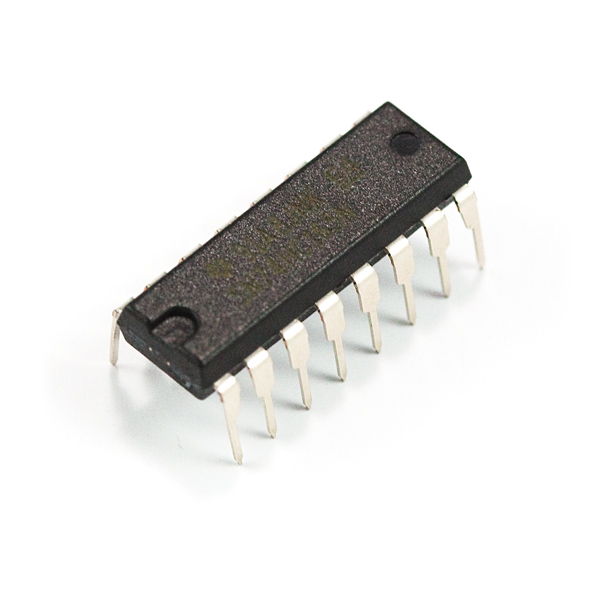
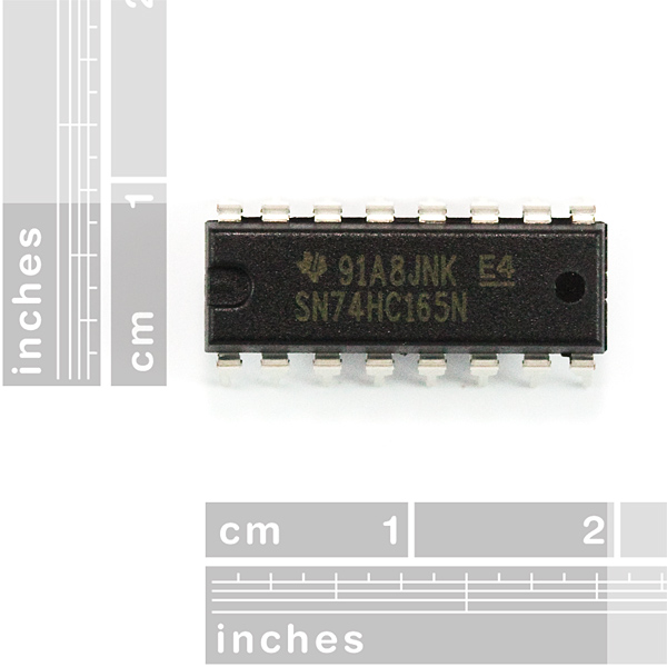
The SN74HC165N is a neat little IC that will take an input of up to 8 parallel lines and produce a single, serial output. You can even daisychain 2+ together to add even more parallel lines. It's a great way to increase the number of inputs on a microcontroller.
This chip works with a voltage supply anywhere in the range of 2-6VDC, and at clock frequencies of up to 29MHz (@6VDC).
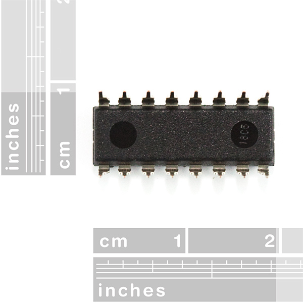
Comes in a 16-pin DIP package.
- Wide Operating Voltage Range of 2 V to 6 V
- Parallel-to-Serial Data Conversion
- Outputs Can Drive Up To 10 LSTTL Loads
- Low Power Consumption, 80-μA Max ICC
- ±4mA Output Drive at 5 V
- Low Input Current of 1 μA Max
- Complementary Outputs
- Direct Overriding Load (Data) Inputs
- Gated Clock Inputs
8-Bit Parallel-In/Serial-Out Shift Register - 74HC165N Product Help and Resources
Core Skill: Soldering
This skill defines how difficult the soldering is on a particular product. It might be a couple simple solder joints, or require special reflow tools.
Skill Level: Rookie - The number of pins increases, and you will have to determine polarity of components and some of the components might be a bit trickier or close together. You might need solder wick or flux.
See all skill levels
Core Skill: Programming
If a board needs code or communicates somehow, you're going to need to know how to program or interface with it. The programming skill is all about communication and code.
Skill Level: Rookie - You will need a better fundamental understand of what code is, and how it works. You will be using beginner-level software and development tools like Arduino. You will be dealing directly with code, but numerous examples and libraries are available. Sensors or shields will communicate with serial or TTL.
See all skill levels
Core Skill: Electrical Prototyping
If it requires power, you need to know how much, what all the pins do, and how to hook it up. You may need to reference datasheets, schematics, and know the ins and outs of electronics.
Skill Level: Competent - You will be required to reference a datasheet or schematic to know how to use a component. Your knowledge of a datasheet will only require basic features like power requirements, pinouts, or communications type. Also, you may need a power supply that?s greater than 12V or more than 1A worth of current.
See all skill levels
Comments
Looking for answers to technical questions?
We welcome your comments and suggestions below. However, if you are looking for solutions to technical questions please see our Technical Assistance page.
Customer Reviews
No reviews yet.
Isn't this the same type of chip that the original NES used in its controllers?
Yes, same type and this serves the same purpose. It's a shift register for inputs, which in the NES controller's case, for buttons.
The one in the NES specifically is the HD14021B for reference.
One of these three are wrong: The description, the datasheet, or me.
Datasheet says that the fastest* "input transition rise/fall time" is "400 ns".
Description says you can run it up to 29 MHz.
My math says 1 / (400 * (10^(-9))) = 2,500,000 Hz (or 2.5 MHz) -- that's more than an order of magnitude slower.
400ns is the CAP on the rise time- the maximum that it should be allowed to be. Faster rise/fall times are allowed, but not slower ones. If you read the note at the bottom of the chart, you'll see WHY slow rise times are bad- if the input lingers in the undefined region too long, it can cause the circuit to double-clock. It also increases the power dissipation of the device, which can sometimes be an issue.
Hey, thanks for the reply!
I guess this leaves me a little bit confused on a couple of counts:
Where does the 29 MHz number in the description come from?
It is the maximum rise fall time (at 6 volts), which I understood to mean (and please correct me here) that the chip could sometimes take up to 400 nano seconds to transition to it's new output state based on the input I send it (is that incorrect?) -- As in: it could go faster, but there isn't any indication from the chip when it does, so if I change it's state and try to read it's outputs faster than 400 nano-seconds (at 6 volts), doesn't this mean that sometimes I will get the old (or possibly undefined) data?
The note at the bottom is specifically related to voltages, not timing -- it says that if I power it in the range of .5 volts to 1.5 volts that it could cause double clocking and incorrect data / undefined states.
Apologies for being a bit of a newb about this. Clearly, there's something here that I'm missing.
I think there may be a tutorial in this- it's a good example of how values in a datasheet can be a little opaque to the neophyte.
Pages 6, 7, and 8 have waveform diagrams and definitions of the various parameters related to them. Basically, the 29MHz number comes from the fastest signal that can propagate through the device without violating setup and hold times and allowing outputs to transition past their threshold levels.
The time to transition to a new state is generally referred to as propagation delay. On page 7, you'll see tpd- that's what you're looking for. The rise/fall time is the time from (usually) 10% of VCC to 90% of VCC or vice versa.
That note at the bottom is both about time and voltage- it relates to the time a signal can remain in a voltage range without causing a problem.
I will definitely try and do a tutorial about this, soon.
Thanks for all the help. I did find this application note about floating inputs http://www.ti.com/lit/an/scba004c/scba004c.pdf -- and it explains the input transition rise/fall rate stuff, and why it's a bad idea to transition slowly (at least I hope this is related!).
I do see the 29 MHz spelled out explicitly in the datasheet now that I inspect it closer (derp!) -- However the math still seems weird to me, using the tPd for 6V still gives me like 31 MHz instead of 29 (It's Megahertz not Mebihertz, right? lol).
As for the tutorial, I did see the original SparkFun tutorial on reading datasheets, but it was extremely basic -- a lot of the terms are still black magic to me.
As for the device losing data if I go "too slow" -- is that only if I transition the voltage between Vss and Vcc (and versa-vice) too slowly or is that if I provide the clock pulses too slowly?
I can use this in place of a CD4021, right?
Yes, the CD4021 is very similar to this one.
Supposedly this part is in Eagle, but I can't find it and a search turns up blank. Anybody know what library it's under?
It's in the standard (not Sparkfun) libraries, try 74xx-us / 74*165 / 74LS165N. (The LS is a different family than HC, but the footprint is the same, and you can always rename the part in your schematic for accuracy).
What if i need to read 8 analog input?Will it work too or do i need and adc on every input before going into the register?
Thanks.
What kind of analog input? Can you describe the surrounding circuit. I think it depends on the current you expect the device to sink/source. What is the meaning of the analog levels, i.e. is it the same as digital level where some range means high and another is low? In any case, you don't need and ADC, if you don't want to connect the analog signal directly to the input, connect the analog signal to a transistor or such and place the transistor output as input to the device.
So there are no way to run this circuit with only 3 cables? I.e. using only clk, ser, and Qh to read? So we also need to manipulate SH/LD?
EDIT: Never mind the question, I didn't think. You don't need ser. So you can run it of clk, Qh, and SH/LD.
Is this the correct shift register to use to control an array of 60 or so LED's?
many thanks
Peter
This is a parallel-in/serial-out shift register, meaning that you can read from the parallel inputs, but you can't write to them, as you would need to do to control LEDs. You need 74HC595s, which are serial-in/parallel-out shift registers.
I think you want some 74HC595's.
[http://www.sparkfun.com/products/733]
Anyone know if/where this part exists in the SF Eagle library?
It would appear not. However, Eagle already has the part in it's libraries.
Just search for 165when you're going to add a part.
And here's a complete code that can be used as a library, reading 16 stages using the same 2 chips as the arduino example above.<br />
<br />
define BTploadPin 25 // Parallel load pin the 165<br />
define BTdataPin 27 // Q7 pin the 165<br />
define BTclockPin 26 // Clock pin the 165<br />
<br />
class Buttons<br />
{<br />
public:<br />
Buttons()<br />
{<br />
pinMode(BTploadPin, OUTPUT);<br />
pinMode(BTclockPin, OUTPUT);<br />
pinMode(BTdataPin, INPUT);<br />
digitalWrite(BTclockPin, LOW);<br />
digitalWrite(BTploadPin, HIGH);<br />
<br />
memset(Clicked,false,sizeof(Clicked));<br />
memset(prevHigh,false,sizeof(prevHigh));<br />
}<br />
<br />
bool Tick()<br />
{<br />
SomethingChanged = false;<br />
<br />
digitalWrite(BTploadPin, LOW);<br />
digitalWrite(BTploadPin, HIGH);<br />
for(int i = 0; i < 16; i++)<br />
{<br />
tempButton = digitalRead(BTdataPin);<br />
if (tempButton == LOW && prevHigh[15-i] == HIGH) <br />
{ <br />
Clicked[15-i] = true; <br />
SomethingChanged = true; <br />
}<br />
prevHigh[15-i] = tempButton;<br />
digitalWrite(BTclockPin, HIGH);<br />
digitalWrite(BTclockPin, LOW);<br />
}<br />
<br />
return SomethingChanged;<br />
}<br />
<br />
void Reset(void) { memset(Clicked,false,sizeof(Clicked)); }<br />
<br />
boolean Clicked[16];<br />
<br />
private:<br />
boolean SomethingChanged;<br />
unsigned int tempButton;<br />
unsigned int prevHigh[16];<br />
};