- Home
- Product Categories
- Sensors
- Geiger Counter (Slightly Less Old-School)

Geiger Counter (Slightly Less Old-School)
Replacement:SEN-10742. The new version has a more robust tube power switch and also supports the Arduino auto-reset feature. This page is for reference only.
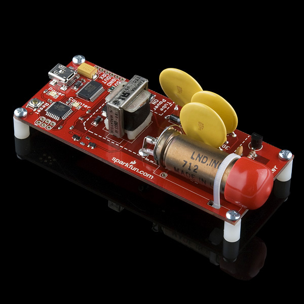
We've revised a few layouts and footprints with this version of the Geiger counter, but it's essentially the same as the last revision. This is a USB powered Geiger Counter equipped with an ATMega328 that can be programmed in circuit using one of the programmers below. Simply plug the unit into USB (make sure you have FTDI drivers installed), open a terminal program to the correct COM port at 9600bps, and you will see random bits being generated from the random background radiation. Each bit generated (actually an ASCII byte, 0 or 1) represents an actual event in the tube in real-time, so the output can be used to deduce CPM or what ever units you need. Here at SparkFun, on average, we get about 25 counts a minute.
Check out the random number generating Geiger counter tutorial for more information.
Also, check out the live Geiger Counter feed from SparkFun headquarters.
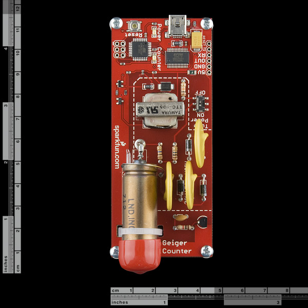
Note: While the Geiger counter is powered and the switch is in the ON position, the board contains exposed high voltage components. In order to turn the unit off, you must flip the tube power switch to OFF while the USB cable is plugged in or while the board is still connected to your power supply. The reason being; when you move the switch into the OFF position, the high voltage lines are bled out through a resistor connected to ground, more information on this is in the tutorial.
A project box or enclosure is suggested. Do not touch the end window of the Geiger tube and do not to touch any conductive region inside the area marked HIGH VOLTAGE when the Geiger tube is powered ON. An enclosure is not absolutely necessary, but if you choose not use an enclosure, remember to be extra careful with the end window and high voltage regions.
The Geiger tube comes with a red boot to protect the end window during, production, handling, and shipping. The boot should be removed if you need to detect alpha particles. However, you should still see activity from gamma and beta particles even with the boot on.
For older revisions with a bleed button: Remember to always hit the bleed button with your power supply connected, after the tube power switch is moved from the ON position to the OFF position.
This product is controlled for export by the United States. Sending it to other countries may still be possible, but will require additional information prior to shipment.
Note: This product is for educational purposes and should not be directly relied upon for determinations regarding one's health or safety.
Features:
- 5V@30mA input
- LND712 Geiger tube
- ATMega328
- FTDI USB
- Power and status LEDs
- TTL output pin from tube
**Replaces: **SEN-09298
- 4.15"x1.75"x1" (without standoffs)
Comments
Looking for answers to technical questions?
We welcome your comments and suggestions below. However, if you are looking for solutions to technical questions please see our Technical Assistance page.
Customer Reviews
No reviews yet.
better start making some more for all of us paranoid people...lol
They sold like hotcakes !
It would be interesting to see measurements from people who bought these devices in the next few days. If people who have them would leave them on and send the hourly counts online it would be a useful (and unfiltered) reporting tool.
Given dominant winds direction, people from British Columbia in Canada and the US west coast could see a rise soon. A way to independently verify what IAEA and Gvt of Japan are saying would be more than welcome.
How do you "measure" as this item is only sending zeros and ones via USB to the termial while a particle is flying through it ?
Here's mine.
Now we just need to get a google earth map going that plots the data and get a few hundred more sensors online!
There's a national (global?) network in place already. See: http://www.radiationnetwork.com/
Unfortunately, the reporting protocol is contained in a PC software application that is sold for $79. The application's input is raw counts into an RS-232 port. See: http://www.geigercounters.com/NetworkVersion.htm
73, Garitron
I like the price of pachube better($0!). http://www.pachube.com/?q=geiger but it doesn't have as many stations in the US yet.
Thanks scubasonar! Took me all of 30 minutes to get my geiger on the net at http://www.pachube.com/feeds/21510. Now I just need a Arduino Wifi shield and I can make it a standalone device.
I live over in the Monterey Bay(California) so I'll try to get my unit on twitter tonight.
Sounds interesting. What's your twitter account? It wasn't listed on your webpage...
Only my hampster and my geiger counter have twitter accounts. Here's the geiger I'm just getting going on right now: http://twitter.com/#!/Geiger93933 and the hampster escaped after I attached a generator to his wheel :x http://twitter.com/#!/georgehampster haha. (The geiger counter is posting hourly hits now but I'm not sure how well the code will hold up, will mod tomorrow!)
How do you do this?
I have this product but I am located in Minnesota.
I do this if someone shows how I could output it to twitter.
I don't want to reinvent the wheel, but here's what I have found so far, if the above user, or no one else replies with a method already designed and running as an executable.
http://www.dustinwheelercpa.com/2010/11/28/how-i-created-my-own-twitter-app-with-visual-basic/
Arduino + ethernet shield + twitter library http://arduino-tweet.appspot.com/ is the quickest route to the tweet (assuming you're not relying on a PC being on all the time). I'm setting mine up using a fez domino connected to the geiger counter and keeping that on my roof. A zigbee chip will send the data down to the arduino every hour and it will post it on twitter. I'll post all the source and images of how everything is setup after it's going.
Reading your post makes me kind of laugh because I didn't really consider the idea of using a PC to do it but ya, that would be pretty convenient I guess! One cable and a netbook instead of a pile of chips. Genius!
Quick Question as I could not find a guide. When connected to the Geiger Counter I get random bits 0s and 1s at random time intervals. My understanding thus far is that the 0 & 1's represent either gamma ray, alpha, or beta particles hitting the tube. Why is there a 0 and a 1 ? Does the 0 mean its one type of particle ? Thanks,
Your questions can be answered in this tutorial, but to summarize, the 0s and 1s represent random bits being generated by the ionizing events. Whenever you see a 0 or 1, an event occured. An event can be alpha, beta or gamma (but be sure to remove the red cap if you want to detect alpha or beta).
Some serious design issues of Sparkfun Geiger Counter
“Waking the sleeping Bear”
First of all I’m a big fan of Sparkfun. I really admire their innovative products, good prices, fast shipments and customer support. I’m a returning customer and will keep on being that. However when you see a mistake it’s fair to do an alert about that so the slip can be rectified. The Geiger Counter, SKU: SEN-09848 has some serious issues.
Even if Sparkfun clearly has notified that this is a product for educational purposes many people, myself included, have the intention to use is for more serious use. Taken into account the recently mishap in Fukushima and the fact that I’m living close to a nuclear plant, I wanted the device to give me some feedback if a situation would arise.
There are three issues with the Sparkfun Geiger Muller Counter (GMC for short). Two are more serious issues and the third is more annoying.
• Incorrect High Voltage • Badly design of detection circuit • Bad placement of the GM tube.
High Voltage! The High Voltage is about 1550 volts if correctly measured. To correctly measure the voltage you will need a voltage meter with at least 1 G Ohms (1E9 Ohms). This is the voltage a zero count rate. The voltage will drop to about 1050 volts a high count rates (> 300 CPS). The GM tube has a recommended operating point of 500 volts and the operating range is specified to in the interval 450 – 650 volts. Operating at 1500 volts will give avalanche and secondary effects and can produces a total ionization of the gas between the electrodes. You can even reach a self-sustaining discharge that will continue as long as the voltage is applied by a single detection event. This region shall be avoided due to that operation here can/will degrade the tube in a longer perspective. Also, the pulse counting will be more or less random and not represent the true counting rate.
Bad design! Due to the HV problem, the designer, not realizing this, had to put in a “heavy” RC filter to compensate for the error in the HV design. The RC filter (R10/C9) gives a time constant of about 8 mille seconds. This in turn limits the maximum count frequency to about 60 pulses per seconds. The actual GM tube can perform much better than that. Typically an event gives a 100uS pulse. You can actually see the avalanche effects (due to running far over tube specification) in the oscilloscope picture in the tutorial on the GMC web page.
Normally a radiation event should give a pulse like this:
www.spectron.us/SM6FIE/Electronics/SparkFunGm/Images/Normal_HV_Pulse.jpg
When the HV is far too high you will get something like this due to avalanche effects etc:
www.spectron.us/SM6FIE/Electronics/SparkFunGm/Images/High_HV_Pulse.jpg
Compare the later picture with the one in the Sparkfun tutorial! With correct HV and detector circuit the GM tube will be able to count thousands of pulses per second. This needs to be redesign.
Bad Placement of GM tube! In the original design of the PCB board it was easy to remove the protection cap of the tube (when you want to do Alfa measurements). Se picture in the tutorial. In the production design the placement of the GM tube was changed. Now it’s very difficult to remove the cap without jeopardizing the extremely sensitive mica front window of the tube. I did this mistake and “puff” the GM tube was destroyed.
It should be a rather simple task for Sparkfun to assemble some instructions and components to upgrade the device fixing the two more serious points above.
Member #115862 in the product thread was on the right track concerning this issue. He also had some point on how to fix the HV problem.
For a more complete report follow the links below:
www.spectron.us/SM6FIE/Electronics/SparkFunGm/Notes_about_Sparkfun_Geiger_Counter.pdf
www.spectron.us/SM6FIE/Electronics/HvProbe/High_Voltage_Probe.pdf
Regards
Bo, SM6FIE
Wow! Thanks for the write up! We really appreciate your work!
I had some uncertainty in the output voltage and never ruled out possible higher values. Like you said, we are advertising the unit as "educational" and really are not concerned with the accuracy of the unit when radiation counts are high enough to potentially hurt someone anyway. Also, the initial design of the unit was for a random number generator, not a scientific grade Geiger Counter (although the design does result in less random results :)).
As for the previous thread about the HV (see above), I discussed this with two other customers and we tried different a few things. Reducing the condenser cap does not work, it lowers the voltage too much. We found that the unit might not be at the correct voltage, but it is enough to measure background events and radiation spikes (up to certain rates). Also, my geiger counter on the feed has been running, more or less, none stop for 6+ months or so, and working great. I can hold my Americium source to it and it goes crazy.
Anyway, the unit does measure counts, like you said, up to about 60 per second. If a condition arose where you were pushing this limit, you would be in danger first of all, and I would agree with you that the accuracy would suffer. However, with measuring background radiation, the CPM is on par with other stations near by and the unit responds correctly to a radiation source. So for it's intended use, the unit works as advertised. But I do agree, the design could use some work to increase the accuracy and overall robustness of the unit.
For any upcoming revision, we will try to address all of these issues. Thanks for your valuable input!
Perhaps a simple solution would be three zener diodes (200 + 200 + 100) volts and a resistor. For example 1N5956BRLGOSTR-ND and 1N5271B-TPTR-ND. Price for the zener diodes is just 20 cents. Then change the RC net, now that the HV supply is correct, and off you go.
I have not tested this solution above but it seems reasonable. Instead I did an adjustable (300 - 1800 v) regulated HV supply to be able to verify the characteristic curve of the GM tube (count rate vs. HV).
The main concern is that the +1500 volt is a factor three over the specification of the tube. In a longer run there is a probability that this will damage the tube. The very heavy total ionization of the gas, due to the high electrostatic field, will lead to an avalanche that in this case can lead to outgassing from the tube materials into the active gas. This in turn will lead to an unwanted ageing effect. This will manifest themselves as protrusions or films (called whiskers'). The practical long term effect is loss of gain, stretched pulses and eventually completely electrical breakdown.
Another effect you can see is pileup, you have to turn of the high voltage, turn it on again, to get the tube to start counting events again.
Regards
Bo, SM6FIE
Very sorry for any confusion, you can contact techsupport at sparkfun dot com for a refund or a replacement with the new revision. Any new stock now as of now will be the new rev using a better switch, which should fix your issue. If you have any problems contact me directly, aaron at sparkfun dot com.
Seconded, I'd be very interested in aftermarket tweaks to improve the design and safety.
Very good ideas. I will be sure to test this in an upcoming revision. Thanks so much for your input! It is much appreciated!
Hello Mr. a1ronzo,
Did you address these issues yet? I'm very interested in your geiger counter as a source of random numbers to one of my computers, but I need a rate of at least ~8k/s. Is your device capable of that as if now, or should we keep waiting for the next revision?
Do you have any idea when this new revision will be put to production?
Geiger counter, O Geiger counter . . . wherefor art thou, Geiger counter? :-(
OUT OF STOCK!!!! WHYYYYY?!?!?!?!?!?!? CRUEL WORLD, PLEASE PUT IT BACK IN STOCK!!!
Any hope of getting these back in stock within the next few years? :-)
I have been running this sensor long term since late March 2011 in Seattle. I graph the data here:
http://nwrs.net/radiation/
The background radiation is generally low and stable, but I do have a very strange event logged on July 4, (up to 705 CPM!!) where i received some very high readings for a half hour, and then an additional blurp about an hour later:
http://seattlewireless.net/~casey/?p=129
After some hours, the CPM of my unit decreases slowly to 0. It stays there even after powercycling the high voltage supply. Only when leaving the HV switched off for a prolonged period, the CPM returns to the normal ~20. But it already happened that the USB bus was not usable anymore after doing this.
What could cause this erratic behaviour?
I bought a Geiger counter last week. For the first trial, it worked well because the terminal program showed '0' or '1'. However, when I tried it after a few hours, it didn't work and serial communication port was disappeared from the host computer, and moreover I found that one IC (FTDI***) which is located next to mini USB connector is VERY HOT. I got burnt on the finger. Because green LED flashes once a few second, some parts may be still alive. I think that USB-serial converter and/or some other parts are broken and must be repaired.
I was wondering if someone could suggest what I have to do at this time.
That sounds pretty much like the experience I had with my first unit. I eventually found a solder blob shorting a couple of traces when I found my jewelers loupe, but the damage had already been done by then. I returned it to SparkFun and they sent me a replacement which has been working fine for months now. I'd suggest contacting SparkFun's support group and getting an RMA number.
Thank you very much for your suggestion. I will send the defective item to SparkFun.
This is a great product, and I was lucky to have ordered it before the geiger counter rush.
This device spits out a random ASCII 1 or 0 on each count, so if you want counts per minute, just count the number of characters received on the serial within 1 minute. I wrote up a python script to do this and http post via curl once a minute on my mac. Its been running constantly since this spring.
I also had the opportunity to accidentally grab this circuit board behind my computer (i though it was a phone) and received quite a zap. I rate it as the mother of all static discharge shocks. No burns, still alive ;)
So, 6 months later they are still on backorder??? When are more coming in?? What's the problem??
It has been a long time....... are you guys designing a new version?
For anybody who might be playing with my VB app, I've updated it to fix one small bug and added a second file output format. You can now specify a filename and have it produce a file that can be read by the free, LiveGraph program, which will graph the output of the last six hours worth of data. Since LiveGraph is in Java and has a published API, you could probably build on that to create your own graphing applications.
I have one point that needs to be clarified about the power switch and discharge on the device. Iv studied the data sheet and when you power it off, VCC is connected to ground through a 10K resistor to discharge the device. My questions:
Is the discharge only done for the users saftey, or is it also protecting components from overvoltage?
If power is cut to the board without discharge, will it destroy the board?
If power is cut to the board without discharge, but is mounted inside of an enclosure, will the user be safe as long as they do not open the enclosure?
The reason I ask is I would want to use this as a addon for a mobile microcontroller in an enclosure run off of a battery and 5v regulator. There would only be one master on/off switch, and this would require that the geiger counter board always be on, and never get switched to discharge.
Thanks for the info! I'm 100% confident now and looking forward to the board B-)
Some helpful notes about using this.
On the FTDI site just look for the automatic setup option and save some time.
To find the serial port for the usb connection (in Win7 at least) go to Control Panel->System->Device Manager->Ports and find the one named USB Serial Port.
Go here and download Putty.exe: http://www.chiark.greenend.org.uk/~sgtatham/putty/download.html
Change the connection type in the first page to Serial and enter the port from the previous step (e.g. COM8), then open.
That is it; you should see 0's and 1's on your terminal, hopefully not too fast! For testing I used some old vaseline glass marbles I had picked up off Ebay a while back. If you do the same remember to test with a UV light to make sure they are legit; they should glow. Actually, now you have another way to test them. :-)
This is a good product as a start to a project. It does what it's supposed to and with some engineering and external components/software can actually be a true "Geiger Counter". Overall, I'm happy with the product and can highly recommend it. But it is not a true "Geiger Counter" out of the box. Firmware that displays CPM is a must... and the 1/0's are useless (without work). BUT... it is a pretty good tube and unless you want to spend 10x as much... it's a great start. Thanks SFE for providing this. I'm enjoying mine and have had very good results after a bit of work to get "real" readings.
However, this should not be marketed as a "Geiger Counter".
nice program works also with sparkfun 9848 !
Geiger Counter Nuclear Radiation Monitor Detector For Windows and Macintosh
http://www.blackcatsystems.com/GM/page3.html
http://www.blackcatsystems.com/GM/download.html
other to be tested under linux MAC in this page:
http://www.blackcatsystems.com/GM/linux.html
interface to IPHONE ?
http://www.flickr.com/photos/nokton/5602623700/in/set-72157626334128931
hack usb java program:
http://www.bidouille.org/hack/geigerusb
Can anyone tell me (or guide me to a site where it tells) how one can update the firmware?
I want to update it to v13 but I haven't got a clue how to do that.
I believe all you need is a copy of the v13 firmware, a copy of the program compiler/downloader for the arduino (from their website) and one of the In Circuit Programmers (ISP) supported by that downloader. I think SparkFun sells a couple of different ISP's, there are two listed in the Related Products here that would probably work.
Received it today, CPM 8-26 (avg 18) indoor.
I am using UniKyrn's VB app to get the data. Has someone written a similar app in C# or Java? Otherwise I will write my own..
Hi :)
CPM 70-120.
This is an abnormal numerical value.
Is there a method of confirming the problem of hardware?
Have you moved the counter to a different location to compare counts? I agree, 70-120 seems abnormally high compared to the average around the country.
Just got a shipping notice!
Had an interesting adventure with my Geiger counter today. My wife had a thallium stress test of her coronary arteries. In the test, they inject a solution of thallium 201 and then use a scintillation counter to see how well her heart muscle takes up the thallium which mimics potassium. 201-Thallium (Tl) is a cyclotron produced tracer with a half-life of 72.5 hr. Tl decays emitting Hg x-rays (69-83 keV) and photons (10% at 135 and 167 keV).
Knowing this little fact, I hauled out my trusty Sparkfun Geiger counter and fired it up to see if I could detect any of those x-rays.
Wow! Baseline here in Tulsa I normally see about 2-3 flashes per 5 seconds on the green LED. However when I had the counter any where near her, the green led was almost solidly on. Scanning it up and down her body I noted a decrease in rate on her extremities and a much higher rate (pretty much solidly on) on her trunk and head. Standing 5 feet away with the tube pointing at her, the rate dropped to about 10 counts / second and at about 12 feet away, I was getting about 3 counts per second.
I have come to the conclusion that I have a very "hot" mama! At least for the next week, or so, anyway. After that, she'll go back to being my normal hot mama!
Ain't nuclear physics grand?
Upon second thought, I wonder what would happen if she were to go through one of those body scanners at the airport. Anybody know?
It's not the body scanner that would trip, it would be one of the radiation detectors. When I had my Nuclear Stress Test a few years back, they asked if I had any travel plans because they'd give me a doctors note explaining why I was radioactive. Border crossings and airports, at least, have a lot of detectors you don't see because they don't have to be close to notice a change.
So, probably I am repeating question from above, but what should be changed in firmware v13, so output to COM port will be CPM? As I can see v13 give counts per seconds, so it should be simple enough, however I am not a programmer... thanks in advance
Can someone explain how to hook this up to an arduino and upload it to twitter, using a wired system, not xbee. Thanks!
You should be able to just take the xbees out of the loop and use the same instructions, connect the tx that would normally go to xbee 1 to the cable that goes to the rx of xbee 2 and vis versa, then connect the grounds together and ignore the rest of the cables that would normally go to the xbee, hope this helps.
By the way anyone know when these will be in stock again?
So, with about 3 weeks of monitoring now, the only visible artifact on my measurements is the occasional DROP in background radiation. :)
http://www.nas-kan.org/mrtg/sparkfungeigercounter.html
Since this is all part of my weather station setup, I've checked a few obvious things like wind, barometric pressure and rain, nothing seems to match up with the changes in background radiation. Yes, I've checked the times I use my dryer also, since the detector is near the exhaust vent for it. :)
Anybody else noticing any interesting things?
With a bit more data history, and weather that actually implies Spring might happen this year, I'm seeing a daily variation in the graph. Roughly a 10% swing between a low at night and the high during the day. Our local star doing its job. :)
Any news on availability, yet? I ordered mne 4 weeks ago. Still waiting. Any estimate would be great.
Thx.
I emailed Nick and he said they will start filling back orders the second week of June. I hope they made enough to get mine!
When do you expect to have more stock available?
availability?
Can this detect xrays??? specifically soft xrays
Real time map with events: radspot.org Currently two locations, would love to add more. Write me @ io@bradley.io for instructions.
Can someone point me to a tutorial on how to upload new firmware to this board?
The makefile in the source has an option to "make program" after you set the device's serial port. However using that the programmer is unresponsive to me. It times out. So there is likely some trick to getting into programming mode.
For those who don't like 1's and 0's, there's some examples of Arduino code here: http://forum.sparkfun.com/viewtopic.php?f=8&t=26559&hilit=geiger+code
In the 60 minute averaging mode, I'm seeing 12 - 18 CPM; usually 12.
Have fun, and post your hacks!
Kevin
For what it's worth, here's the conversion numbers I'm using based on reading the spec sheet for the tube and various and sundry internet resources. Remember, as others have pointed out, there are big differences between alpha, beta, and gamma, as well as far too many other factors to easily summarize. All this counter is good for is to estimate exposure...
* For the ND-712 tube used in the Sparkfun geiger counter, we know the following dry air dose rates for Co60 gamma response:
* 10^0 CPS = .000055 R/hr (Roentgen)
* 10^1 CPS = .00055 R/hr
* 10^3 CPS = .055 R/hr
* The next step ramps up sharply. Time to run...
* 10^4 CPS = 4 R/hr
*
* Using the following conventions, derived as best I can from various internet sources:
* - assuming dry air exposure
* - assuming gamma
* - using that assumption, Roentgen converts to the following absorbed dose equivalents:
* - 1 R = 0.877 rem
* - = 0.00877 Sievert
* - = 0.877 rad
* - Some simply round to 1 R = 1 rad = 1 rem. I've used the .877 factor... change as you see fit!
I have some questions about the schematic: what is the role of the audio transformer and where the high voltage came from ?
Thanks.
Just as a prototype to see if it would work, I fired up an old copy of Visual Basic and hacked something together to read the 0/1 coming from the USB Serial port and graph the results.
Image: http://www.nas-kan.org/geiger.jpg
Source: http://www.nas-kan.org/SparkFunGeigerCounter.zip
UniKyrn, I tried your program and it's great. I love the graphing capability. But, there is no way to interface it to get the data out onto the Internet. It's MUCH better than 1's and 0's!!! Thank you for making this available!
Let's all make it better...
SFE... are you up to helping get all the Geiger counters you've sold set up with software so we can upload the data and track it?
I tinkered with the program a bit more and now it includes a min/ave/max display of the readings. My own goal is to add a file picker to it so I can get it to write out the count info to a file that MRTG can read, so I can add graphs to my website. It should be possible to dump the output in about any format somebody would want with a little code in the 1 minute timer, and then export that info using whatever external app you wanted.
I've left the program running all weekend here now, the ave count for Otis Orchards, WA appears to be 21 CPM, right in the range I expected to see. We're sitting over granite and old river beds here in E Washington, so we get a bit of Radon. The counter is currently in my second floor office at home, I might put it in the basement and see if the readings change.
Ok, it's a insane hack, but it seems to be working. Using the Windows program to write out the results and MRTG running on OpenBSD, I've managed to graph the Background Radiation for my website.
http://www.nas-kan.org/mrtg/sparkfungeigercounter.html
The current zip of the software includes the hack to write the results out to a file for MRTG to read.
When do you expect to have them back in??
I'd sure like to know, too! Eagerly awaiting mine. Also, my order status is a bit confusing. It says "shipped," but the details still offer me a button to settle the balance. I hope I have one forthcoming...
Maybe I am missing something here. Could someone check my conversion?
For the ND-712 tube used in the Sparkfun geiger counter, we know the dry air dose rate for Co60 gamma response:
18 CPS/mR/hr
Therefore: 1080 CPM = 1E-3 R/hr;
Given 1 R = .00877 Sieverts,
then 1 CPM = 0.00812 uSv/hr
Does this makes sense for a conversion factor? What are people using?
Since the LND-712 tube used on our Geiger Counter does not distinguish between charged particles (alpha, beta) and EMR (gamma), there are different conversion factors that will give Sieverts. Charged particles have different energy values than gama rays and correspondingly different scale factors. Reference here.
Also, sieverts depends on the biological tissue affected which also changes the conversion factor.
Overall, without a proper filter, the SparkFun Geiger Counter is not able to give an accurate sievert measurement.
Pulses uS/h for LND based on Cs137 and measured in a Lab
cpm
0 0,000
5 0,038
10 0,076
25 0,190
50 0,381
75 0,571
100 0,761
111 0,845
371 3,498
1298 14
4603 57
25707 360
50000 700
75000 1050
100000 1400
Have fun at funspark !
Member 115862,
My above conversion factor of 0.00812 uSv/h/CPM based on tube's Co60 specs is about 6.5% higher than your lab data based on Cs137. Your data gives a factor of 0.0076 uSv/h/CPM. Can you tell me a little about the provenance of this data?
Also, I have a Windows XP console program that puts out a table of CPM, uSv/h, uSv cumulative, elapsed time, etc., for Sparkfun geiger. Can select various formats, beeps, sample rates from command line. Email me and I can send you the C code and .exe. mike@treehouselab.com
Finally... after so many months asking for help (the original post isn't online but it's been more than half a year) to get a usable program that outputs usable data... treehouse has come to the rescue! It works and it's awesome! No more 1's and 0's that mean NOTHING when what we ALL want and NEED (at this time) is a SENSOR and not a random number generator. I am SO SORRY it took what it did to get a response. We should have ALL been ready before a disaster happened. Going forward... is everone here ready to take "radiation" seriously and start writing some code?
I'm not a programmer... I'll admit that. I take what I can find and use it and what code I can find or write (I do some) and end up with something useful.
SFE... really? The firmware should have had CPM at a minimum out of the box!. 1's and 0's...? and no easy way to update the firmaware??? ...enough said.
SFE, please step up to the quality of software treehouse has made available. It makes your sensor useful.
Thanks for your input heathkid!
As mentioned above, a random bit (actually an ASCII byte) is generated for each event in real time. You can basically ignore the "random number" terminology. When you receive a byte on the serial port, that byte corresponds to an event in real time within the tube. Also, there is firmware written that display CPM in the github repo. Overall, the firmware was designed to be lean and for the user to post process in anyway they see fit.
That being said, the next build of Geiger Counters will have a CPM output, since that is overwhelmingly being requested. :)
Just to confirm, the latest build comes with random number output.
On a second thought, I like the random number output :) If I want CPM (CPS is useless anyway), I can calculate it with Arduino or an app on PC.
We are certain to die from radiation, but unfortunately this detector doesn't detect the kind that's going to get us. What we really need is a UV radiation meter.
Light is not radiation. Anyway, sunblock is cheap enough.
Actually UV light IS radiation. Gamma radiation and UV radiation are both electromagnetic radiations. The difference is that Gamma radiation has higher frequency 10^20Hz vs. 10^16Hz of Ultraviolet.
I just bought 2 of these. Out of the box, one reads 30% less CPM than the other. I am getting an average 14 CPM out of the high one, for 60 sec sample periods.
Also, the conversion factor I keep reading of 0.00233 uSv/hr/CPM, can anyone show how that is derived from the LND-712 specs?
I was buying 2 of them and I have some comments :
1.) The hardware is ok. But there is a severe issue regarding
the Voltage beein fed into the tube ! I measured 900(!) Volts
with a Fluke Meter and that's far too high for this LND tube ! LND describes the plateu of the Geiger-Mueller Tube in between 400 and 500 Volts. Higher Voltage will destroy the tube and shorten life dramatically. So I changed the 10 uF Condenser (right one near the diode in front of the transformer) to a value of 1uF and I get 430 Volts, best range for the tune.
2.) The software is ugly ! I expected the values of microSievert/h or the Impulses (counts) per minute or second sent via the USB port. But they send zeros and ones while the tube is affected. Useless as a measuring instrument. I am working on a different processor to bring in with a software sending either the cps periodically or the microSievert/hour also.
Fritz
1) I am interested in how and where you measured that voltage. Please email techsupport@sparkfun.com so we can verify what is going on. With of the boards we have sold and tested, we have never seen that type of behavior.
2) First, computing Sieverts is not trivial (i.e. simply multiplying by a scale factor) without a proper filter on the end window. Aplph, beta, and gamma will each have different scale factors. Second, to measure CPM, you can extrapolate that value from the bits generated. As mentioned above, a random bit (actually an ASCII byte) is generated for each event in real time. You can basically ignore the terminology, in other words, when you receive a byte on the serial port, that byte corresponds to an event in real time within the tube. Also, there is firmware written that display CPM in the github repo. Overall, the firmware is lean and designed for the user to post process in anyway they see fit.
Hi Aaron,
you are saying there is firmware with CPM in the repository, but at least in the beginning of the file there is still counts per second, every second (v13). Is there something newer than v13?
The video measuring the Voltage on the tube with a 1uF condenser
instead of 10uF in the circuitry of the toggle ramp produces 500V instead of 900 Volts.
http://www.youtube.com/user/studio10mhm#p/a/u/0/HS3FpkDWSlk
Fritz
As far as we can tell, the voltage for the Geiger Tube is within spec. Measurement of a high voltage, high impedance connection is not trivial, so we must infer the value as shown in the tutorial. Thanks for looking into it though!
-Aaron
Fritz. Thanks for the input! We will look into the issue. Thanks!
Yes , I will do it again on the weekend and send you what tools I used via a video.
Fritz
I put together a few GPS enabled units & am tracking events. Check out http://radspot.org for a real-time monitor with counts. You sometimes see simultaneous events at a distance which may imply a particle shower.
I took a closer look at this design and I have a few questions.
First, the geiger tube is specified to operate at 500VDC, with a range of 450V-650V. My measurement of the Sparkfun board yields 251.5V, half the nominal voltage. This drive voltage is far outside the specification of the geiger tube, and so one cannot depend upon the specifications of the part. (the specs of the geiger tube are actually quite good. It is exceptionally linear for many orders of magnitude difference of radiation). My question is: have Sparkfun folks actually measured a calibrated radiation source?
Second, the transistor Q4 is being driven without bias from an AC-coupled source (the geiger tube), and my measurements show the base is being driven to -12VDC when there is an event, but the reverse breakdown voltage for the base-emitter junction of a MPSA18 is 6.5V. It seems to me a clamping diode is required.
Regarding measurement of the 500V, it was covered in the tutorial but I had to think about it again too. When you are putting your meter in between the tube Vcc and ground (tube case) you are making a voltage divider with the 10 Meg resistor. Normally you don't have to think about the impedance of your meter much since its usually so much higher than anything normally measured.
Christine, please make a drawing and make it official her. I will redesign my 2 geigers if necessary.
Can this be battery powered? If there's no USB connection, can it be powered by 5V through either the programming socket or JP2? On the spec sheet (v19) I don't see any obvious reasons why not, but I'd like some knowledgeable input before cooking a $150 toy...
Thanks!
Kevin
is anybody interested in implementing cryptography into this device so the readouts could be authorized by certain authority - to prevent spam measurements ? Like signing the message with RSA/DSA a sent in in plaintex as cryptogram so nobody can fake the measurement. It would need to allow to upload the public keys for signing via serial port by companion uprocesor (from multiple trusted authorities - we cant trust to single network in this dark ages)
also the source code for this needs to be public domain to be usable. If anybody interested in putting this code http://www.netmite.com/android/mydroid/cupcake/system/core/libmincrypt/
into AVR i'm in. Wanted to do this before but never had enough of time...
i've setuped a git on public hub http://repo.or.cz/w/avrrsa.git
i'll commit my previous work (related to mincrypt) - i've just got it working :)
sorry, only for signature checking. not helping me a little
maybe this project can help
Open Sensor Network - osnd
lightweight network daemon serving those purposes:
1.) providing unified interface for various sensor (either via network or via plugin)
2.) log data supplied from varius sensors into database
3.) serve request from other OSN network nodes (or dataminers) - either realtime, or from the database (with maximum history setting)
properties:
1.) must be portable - cause needs to be embeeded to networking hw (routers, AP and other networking computers)
2.) must provide option for secure data transfer between peers. Private public cryptography should be used. Every instance of the osnd will have its own private and public key (accessible wordwide) . Private key is used to sign the sensor data so authenticity of the source of data cannot be compromised.
https://spreadsheets.google.com/ccc?key=0AubZ5tYkp5yhdG10Sl9ZRFEtV2EwNl9EV3ZOQm9uLXc&hl=en&authkey=CLWYm64D
Here is some hourly averaged data from Alsea Oregon over the last few days:
Date hh:ss Average CPM
2/17/2011, 19:00 28.7
2/17/2011, 20:00 29.2
2/17/2011, 21:00 29.1
2/17/2011, 22:00 26.6
2/17/2011, 23:00 24.1
2/18/2011, 0:00 27.2
2/18/2011, 1:00 27.4
2/18/2011, 2:00 28.3
2/18/2011, 3:00 29.1
2/18/2011, 4:00 29.9
2/18/2011, 5:00 28.2
2/18/2011, 6:00 29.0
2/18/2011, 7:00 29.2
2/18/2011, 8:00 30.1
2/18/2011, 9:00 29.4
2/18/2011, 10:00 32.3
2/18/2011, 11:00 27.9
2/18/2011, 12:00 30.0
2/18/2011, 13:00 29.2
2/18/2011, 14:00 30.5
2/18/2011, 15:00 32.0
2/18/2011, 16:00 29.1
2/18/2011, 17:00 28.6
2/18/2011, 18:00 27.7
2/18/2011, 19:00 28.1
2/18/2011, 20:00 28.7
2/18/2011, 21:00 31.7
2/18/2011, 22:00 27.7
2/18/2011, 23:00 29.1
2/19/2011, 0:00 27.8
2/19/2011, 1:00 29.7
2/19/2011, 2:00 30.5
2/19/2011, 3:00 29.2
2/19/2011, 4:00 31.0
2/19/2011, 5:00 31.1
2/19/2011, 6:00 29.9
2/19/2011, 7:00 33.4
2/19/2011, 8:00 29.0
2/19/2011, 9:00 31.6
2/19/2011, 10:00 31.3
2/19/2011, 11:00 32.5
2/19/2011, 12:00 28.5
2/19/2011, 13:00 31.6
2/19/2011, 14:00 29.2
2/19/2011, 15:00 31.5
2/19/2011, 16:00 29.2
2/19/2011, 17:00 28.2
I also setup a twitter feed called AlseaORGeiger if anyone is interested in monitoring the feed.
Nice indeed, I've also been recording data for a while. It would be interesting to collect data from different locations using standard protocols and publish it.
This is what I've collected over the past few months in Europe: http://hb8.be/geiger/
Anybody knows how to convert CPM into Sv?
After poking around the comments and documentation for the radiation reporting being done on pachube.com, it appears that the LND-712 Geiger tube conversion factor for CPM to uSv/hr is .00233
I have no idea how one extracts that from the LND-712 datasheet at http://www.lndinc.com/products/348/
Anybody know?
Since the LND-712 tube used on our Geiger Counter does not distinguish between charged particles (alpha, beta) and EMR (gamma), there are different conversion factors that will give Sieverts. Charged particles have different energy values than gama rays and correspondingly different scale factors. Reference here.
Also, sieverts depends on the biological tissue affected which also changes the conversion factor.
Overall, without a proper filter, the SparkFun Geiger Counter is not able to give an accurate sievert measurement.
That is some seriously beautiful data. Here are some links to monitoring sites if anyone's interested:
Yup, the higher the elevation, the more background radiation you will receive.
18 Counts per minute from Virginia (Northern)
If I backorder now, which version of firmware will be burned? v12 or v13?
If I can just put in my $0.02 worth: I think it might be better to create a new version of firmware that outputs via USB the number of counts per minute, each minute.
For my implementation, I used a Basic Stamp 2. I picked off the OUT signal off the header holes on the edge of the board. I then count the number of events in a minute, and send that number to my linux box via a RS-232 serial port. I also modified a few perl scripts to calculate the average CPM over the course of an hour and automatically upload that data to twitter via ttytter.
I can give more details if anyone is interested.
I was surprised there were any left when I ordered.
I'm in the Central Coast range of Oregon, not too far from Corvallis. I will post data tomorrow, but a first test yielded 820 events in 30 minutes, or about 27 CPM. Folks can also look at http://www.radiationnetwork.com/ for levels in their location.
I'd also be interested in software to feed twitter if someone is feeling creative. I might hack something together myself though.
This is a nice board, but I'm trying to figure out how long it could run on battery. Is that 30mA number a reliable average?
Also, it would be great to see a BOB-only version. Basically, just page 1 of the schematic with a simple 3-wire GVS interface (Ground/Voltage/Signal). I've already got an MCU on my project that can monitor the signal, and I don't need the USB interface. But I do want to minimize power consumption for long monitoring times.
Here is the location of the latest v13 firmware:
https://github.com/a1ronzo/SparkFun-Geiger-Counter
That version still only emits 0's and 1's; I've never seen the "counts per second" triggered by a timer overflow.
Looking at the code for v13 from the above site, line 7 clearly states Displays counts per second, every second, and line 46 prints counts per second on the screen.
I am a newbie, so am I missing something?
Does the v13 firmware whose location is shown above need to be loaded into the ATmega368 to give CPM using HyperTerminal?
Plugged in out of the box I get 0 or 1 with each count registered by the on board LED.
Newbie to this so appreciate the help.
I ordered one and waiting for it to ship to me in Tokyo. As you can imagine, given the tragedies of late, I am more than looking forward to receiving this unit! Please post more on the v1.3 firmware mentioned above. I too don't care about random numbers at this point. Will I be able to see CPM out the door?
I'm curious to see how this unit compares to the following : http://strawberry-linux.com/catalog/items?code=53001
I am also in Tokyo, and have one unit in backorder. It would be interesting to set up a couple of these in a network, to use as an "early warning system".
Hope they get the units back in stock soon.
Same here.
I REALLY couldn't care more for the 'Random Number Generator' part. Can I just order these and combine it with Processing or such and an Arduino, to text(or tweet/orso) me (or sound an alarm or such) if the radiation levels go up?
Even with the random number generating firmware, you can deduce CPM. Whenever a random bit is put on the serial port, that corresponds to an event in the tube.
True, but CPM would be more useful for most users, particularly at this time.
I am unclear as to whether v13 provides CPM output? What version of firmware ships with the unit?
Thanks,
Mitch
I've started a thread over in the forum. Maybe best to move discussion on the FW over to there rather than in these comments. Just search for the part number "SEN-09848" in the forum.
Random number generation aside, you can always get particle count out of this device, either via serial or digital output. It would be easy enough to write an Arduino or Processing sketch to count particle hits per minute or hour, and sound an alarm if it's above a set level.
In a future revision, for a safer and fully automated high voltage discharge, the manual switch could be replaced by a high voltage (1000V) depletion MOS transistor such as IXTY08N100D2 (DigiKey have them).
The source is connected to +5V, the drain is connected to the bleed resistors and the gate is connected either to ground or to an ATMega328 IO pin.
Since this is a depletion MOS, it conducts when the source-gate voltage is zero, so while the device is unpowered, it ensures the bleed resistors are on. When the device is powered and the gate is pulled to ground (-5V relative to the transistor source) it stops conducting and allows normal operation. If the gate is connected to an IO pin, it additionally allows the processor to control the deactivation of the bleeding resistor (in this case, another IO pin connected to the base of Q3 could prevent the HV generator from oscillating when connected to +5V and allow it when configured as an input).
Would this pull the 5V power bus above spec when the device was switched off? Even just a spike could damage '168 if it goes high enough. I'm not an expert enough with ESD-like risks to know if the digital parts would tolerate this, or if the regulator would absorb the spike even while unpowered.
According to the site... "v13: outputs counts per second, every second". Can someone please post a link to that firmware? I can't find it. CPS is much more useful than the random 1's and 0's currently generated. Thank you.
I'm thinking this would be a very interesting item to add to a weather station.
What is the expected life of the tube?
Is the life of the tube reduced when energized?
Is there any reason why it couldn't be powered up 24/7?
Thoughts on breaking out the GM tube on a thin bit of coax or other appropriate cable, maybe via a tiny BNC connector? One could enclose the signal processing & HV (tube bias) bits for safety & durability and let the tube wander into harms' way.
I need one of these and some calibration sources; it'll go great with my Civil Defense survey meter, dosimeter, & reader/charger. Now I'm tempted to break out my copy of Knoll's "Radiation Detection & Measurement" and see what kind of a fun tutorial I could come up with.
There actually is enough energy stored in the high voltage capacitors to be more than just annoying. Once the power switch is turned off it will discharge quickly, but there is no need to keep it connected to the power supply or USB cable. The hazard would be if you unplug it from it's power supply but forget to turn the power switch off. In fact unplugging it and then turning the switch off would be safer because the only path to ground would be on the board itself.
Assuming the on/off switch is the same as COM-00597, it's only rated for 12V and has a low dielectric strength rating of ~100V. Putting 500 volts through this switch makes this design live up to the SparkFun name. Personally, I'd use a long stick to turn this thing on/off.
The On/Off switch used on this design is not the same as COM-00597. We have sold many of these boards for a little over a year now with very few issues. As long as you turn off the tube, there is nothing to worry about, and even if you happen to forget, the energy stored on the caps is still very low with a properly functioning unit.