- Home
- Product Categories
- Development Tools
- ArduIMU+ V2 (Flat)

ArduIMU+ V2 (Flat)
Replacement:DEV-11055. We've run out of the V2s, but you can still get the latest version! This page is for reference only.
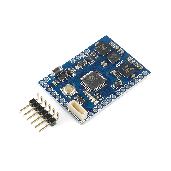
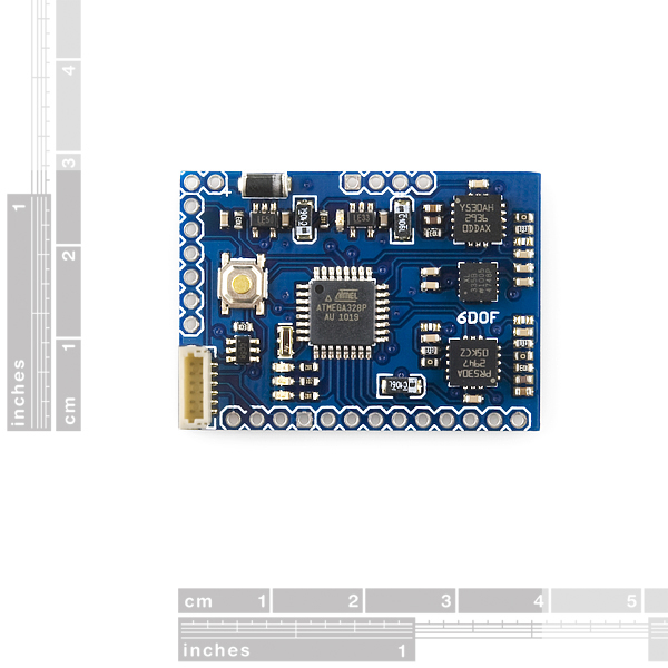
Why "+" in the name? Because it's an Inertial Measure Unit (sensors and hardware filter circuitry) *plus *an Arduino-compatible processor that can run Attitude Heading Reference System (AHRS) code, based on Bill Premerlani's DCM algorithm. This hardware consists of a 3 axis accelerometer and three gyro sensors, dual power regulator (3.3v and 5v), GPS port, an Atmega328@16mhz and a lot of status LED's. This IMU can serve as a replacement for ArduPilot's thermopile sensors with the 2.51 code and above. This IMU improves upon the first release in that the high-pass filter, which was reducing the effeciency of the DCM code, has been removed.
Note: There is a new version of this board available, however, we have a handful of these left in stock so get them while you can.
- 3 Axis Accelerometer
- 3 Axis Gyroscope and Accelerometer
- Arduino Compatible
- Source Code included and Open Source
- Power LED (Green)
- Status LEDs (Red, Blue, Yellow)
- 1 SPI port
- 1 I2C port
- Two PWM outputs (for servos)
- GPS port (uBlox ready!).
- Protection diode
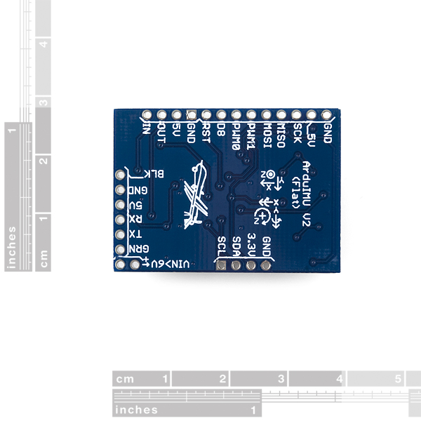
- Serial port output with servo standard connector for easy interface with any device (Ground, 5V, TX-OUT)
- Manual
- Schematics
- Board Diagram
- Code
- ADXL335
- LPR530AL (dual)
- LY530ALH (single)
Comments
Looking for answers to technical questions?
We welcome your comments and suggestions below. However, if you are looking for solutions to technical questions please see our Technical Assistance page.
Customer Reviews
No reviews yet.
This looks kind of similar to this IMU I found
Mongoose
I'm thinking that having a magnetometer is key to eliminating drift in the yaw. I understand that I can eliminate drift in the pitch and roll axis by using the accelerometer to detect the direction of gravity, but how do I eliminate drift in the yaw without having a magnetometer in an application that is mostly stationary? How are the rest of you arduIMU users doing this?
Just wondering when you might be getting these back in stock.
I am looking at the DCM algorithm code re-implementation at http://code.google.com/p/ardu-imu/source/checkout. Does anybody know if this codebase supports dead-reckoning based on an absolute (GPS) or relative coordinate system?
It appears that some initial implementations of Bill Premerlani's DCM algorithm had dead-reckoning (http://code.google.com/p/gentlenav/source/browse/trunk/libDCM/deadReckoning.c?r=591) as part of MatrixPilot, but it's unclear whether even that implementation supported dead reckoning in non-GPS situations (ie magnetometer).
I'd like to precisely track the relative location of an object indoors, as well as its pitch/roll/yaw. Any guidance would be appreciated.
-Ben
Can this one be easily interfaced to a BluetoothMate or similar? Can it be powered with a Lipo?
Check the 'manual' link above. You can't directly use a lipo, you will need higher voltage. check out our lipower or powercell for boosting the voltage of a lipo battery.
it has a header for an FTDI cable, which has the same pinout as a bluetooth mate.
Hi,
I have three questions:
It seems that the FTDI-USB cable suggested in http://code.google.com/p/ardu-imu/ does not work properly with this board, based on their troubleshooting comments.
I wonder if it works fine with Sparkfun's FTDI basic breakout 3.3V?
Secondly,
Is it possible to receive the raw accelerometer and gyro sensor results directly to the PC by serial port?
Third,
Is it possible to get the serial data via the same FTDI-USB port?
Thanks very much
As far as I can tell Im doing something unique to try to run a blimp drone with this, 4 IR sensors, 1 ultrasonic sensor, and a dual band motor driver. Any bread crumbs would be appreciated.
can somebody please help me find some info about the code that this comes with by default. I did not upload the arduimu code or anythin. Just out of the box, what is the code in this one? Any help wud be appreciated much
Follow the link for "Manual" in the link above and it will walk you through initial setup and troubleshooting. Once you get the code running you can play with it while you figure it out.
Hints:P If you want to first put BLINK on the arduimu first (just like any other arduino) LED pins on arduimu are 5, 6, and 7. Load the older arduimu_v1.7 with your FTDI cable. This will let you play with a cool telemetry tool that comes with the utilities (not compatible with newer _v1.8.1 output format?) This tool is nicer than using the serial stream in the arduino IDE and it has a pretty cool visualization that can be run with a bare arduimu. SAVE TIME (30s per reset to calibrate) by setting ENABLE_AIR_START 1
I´ll look at using this IMU to develop a generic vehicle logger unit. This will store sensor values, GPS data, realtime clock data so that the log can be post processed to allow post analysis and re-play of what happened during vehicle progress. This can be of great interest to for example sport motorcyclists and other sports vehicle pilots. One could think of post rendering of progress as a Goggle maps overlay or Google Earth playback. My own engineering contribution will be limited to developing of the logger. There are many out there capable of doing fancy post processing presentation of the logger data so I hope I can find a partner there in due time. I was thinking of a graphical overlay that animate the vehicle/rider in relation to sensor values in relation to a map. If you have an interest in this topic feel free to let me know if any cooperation is of interest.
Gunnar, have you had any luck on this project? I'm thinking about building a product like this for flight schools and pilots.
Cool Idea.
does anyone know how I can connect a non-ublox GPS? i am making a PCB to attach to the bottom, on which pin can i connect to my gps's serial TX?
Check out the forums on the Media-tek 3329 from DIYDrones.
See this thread:
http://www.rcgroups.com/forums/showthread.php?t=1234310
for using the remzibi osd gps (and similar)
Is the GPS connector a 6 pin JST like the new assemblies you are selling? I am plenty excited about those, too. My eyes are getting too goofy to enjoy making little connectors any more.
@bash- get a look at the ardu-imu website for info the board. You program this like an Arduino with the standard Arduino IDE, but it needs a usb to serial translator to hook up, like the Arduino Pro that SF has; the DEV-09716 ought to be the ticket. They have a wiki at the ardu-imu site, and you can see how the parts are all hooked together in the schematic.
The GPS connector should be purchased with you GPS
Wow! This looks like a great thing to get! All these gyros and accelerometers make me think that programming this thingie will be fun!
How is this Arduino compatible? I mean, is there a special IDE for this, or is it that the ATmega328 pins are already connected to all these gyros and parts?
I can't wait to get this!
Yes you can use the arduino IDE. Its basically an arduino due without the usb and with some of the pins used for talking to IMUs and others reserved for things typically used with IMUs like a GPS and magnetometers. You can run other sketches too, or your own customized version of the base adruimu sw set but Id be interested to know who is using this in an application that is not flying. In a stripped down system it as the only micro controller that's my goal for the blimp project im in the middle of) or you can hook it up to other micro controllers.