
Lessons from Rebuilding Illumitune
A few SparkFun engineers have been volunteering their time and skills at a local kid's museum called World of Wonder (WOW). It's a great challenge: Building electronics is hard, building electronics to last a week at a kid's museum is nearly impossible. I have a new found respect for exhibit builders and museum caretakers. Maintaining these exhibits is a full time job.
When I first started a few months ago, the museum staff didn't really understand what skills we brought to the table. My first assignments were to fix simple things: Can you make this button work? Can you take a look at this broken train whistle? Yes! I can help with that.
Once the museum staff saw how we operated, they got more bold with their requests: Can you fix this gigantic exhibit that plays music based on some sort of invisible beam and displays different colors? We don't have any schematic, firmware, contact information, or supporting materials. Uh, sure! I can take a look...
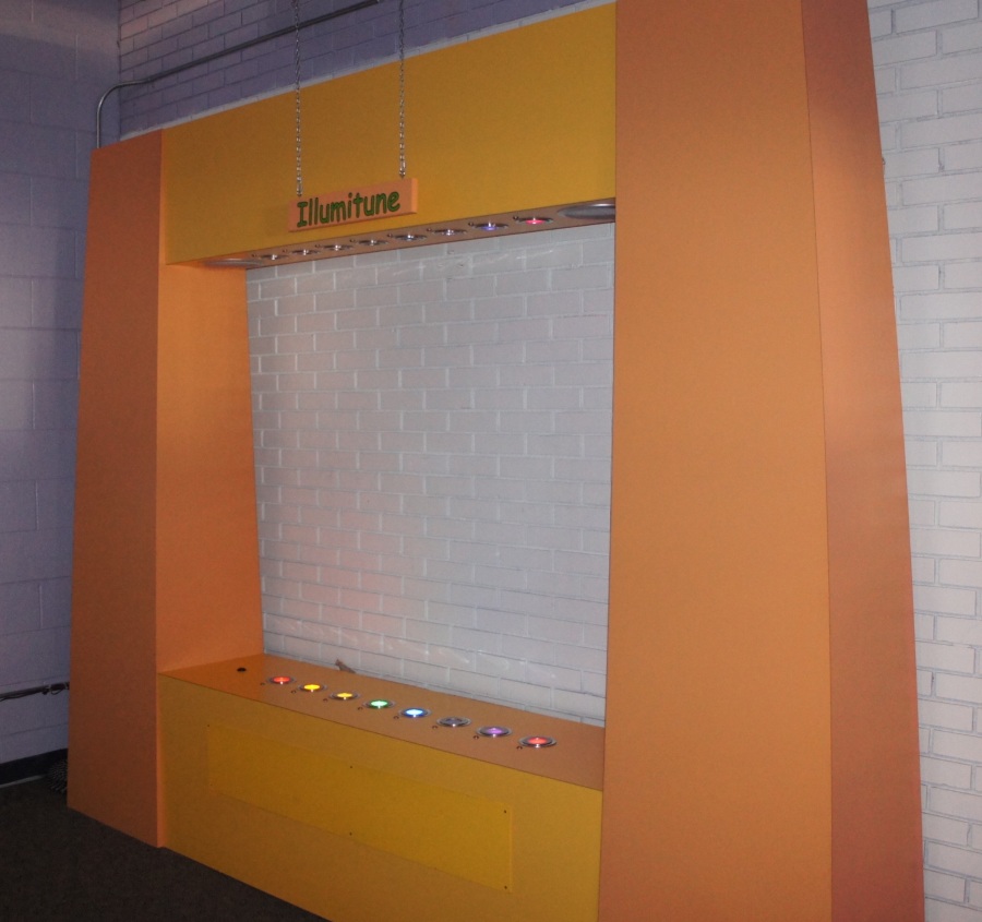
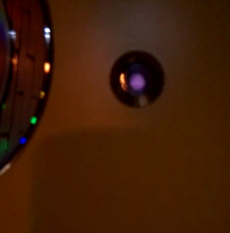
Here is the exhibit in all its glory. The following is the story of the 3 month adventure to fix the Illumitune Infrared harp. Let me start with some of the lessons learned:
- Document your work
- Use polarized connectors
- Buy pre-made cables
- Label stuff
- Leave the debug cable in the unit
- Give me some debug information
- Own a logic analyzer
1) Document your work. Realize you won't be around next month so please leave behind everything you can to help the next person support (repair) your work. Things I now leave inside the actual exhibit: clear schematics, a wiring diagram, an overall layout, all the firmware on a jump drive, operation instructions and maintenance information for the museum staff, and contact details (my name, my email, cell # if needed, etc).
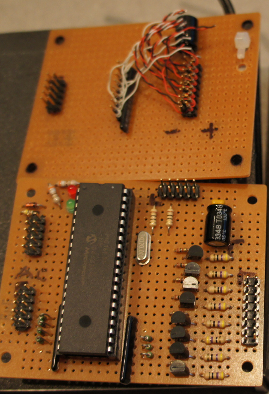
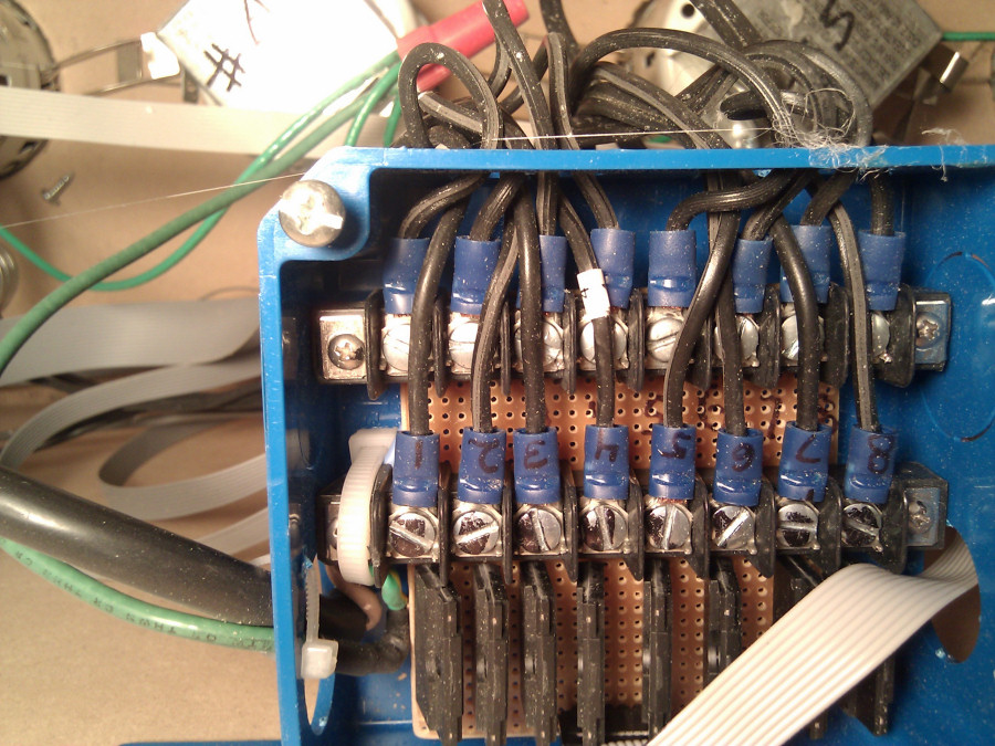
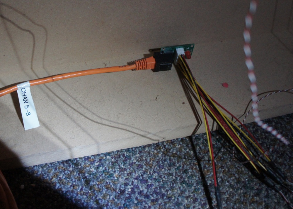
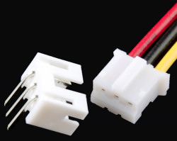
2) Use polarized connectors. This may seem silly but I've seen a lot of projects where the creator soldered wires point to point. See the clump of black, red, and white wires in the left image? Those wires originally connected the IR receivers to that perf board - wire wrapped then soldered. Not only is this slow, it is unmaintainable. You should always be able to remove a board or sensor by unplugging the various wires. This makes it possible to swap out parts to determine what might be broken, increasing the speed of debugging. Furthermore, you should always use polarized connectors. If the staff need to relocate a piece to a different part of the museum, asking them to decipher and follow a thin sharpie mark on a perf board (see the lower left image? Where's pin 1?) is dangerous. Polarized connectors will help prevent your piece from sitting unused in the back room.

3) Buy pre-made cables. This goes hand in hand with the polarized connector lesson. You should not be running down gremlins (aka problems) in your wiring harness. Use premade cables that you can trust. I personally love to use CAT5 cable: it's cheap, readily available in many different lengths, and you can even get different colors! If multiple of the same type of cable run into a board then throw the cable color ("Red") or cable name ("IR2") on the PCB for easy identification. I also use the SparkFun JST assemblies by the handful. Buying these pre-made cables and connectors allowed me to concentrate on bigger problems then getting my crimps correct.
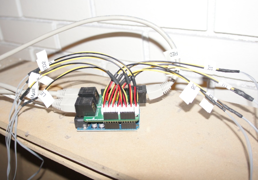
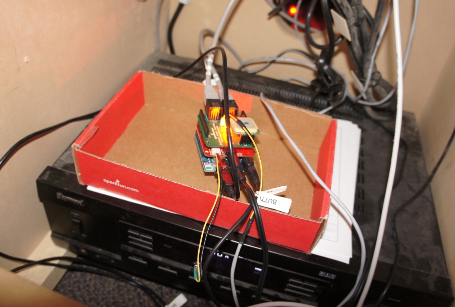
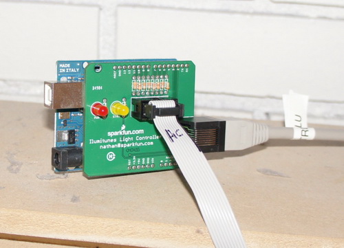
4) Label stuff. This is perhaps the greatest lesson I have learned from working on Illumitune. On a complex piece there will be large amounts of wires running everywhere. A $30 label printer will save your sanity and the person who looks at the piece after you. Label everything. This is obviously a USB cable, but what does it go to? Main controller debug 38400bps would be a great label. "IR LED 4", "Red to Detectors 1-4", "To Light Controller" are all great cable labels.
5) Leave the debug cables in the unit. Illumitune had a total of 4 microcontrollers. At any given time I needed to reconfigure two of them regularly. I had the idea of running USB cables from the boards down to the side access panel. I left these USB cables permanently installed in the exhibit. This was awesome! It saved me from having to climb a ladder and plug in a USB cable every time I needed to debug the system. By leaving the 'debug cable' in your exhibit you also increase the odds the next person to maintain your exhibit will be able to connect to it. Please don't assume that next user will be able to connect to the three odd spots on your perf board to get to TX/RX/GND. By leaving a standard USB A-to-B cable in the exhibit I assume that USB ports will be supported for the next 3-5 years.
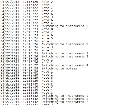
6) Give me some debug information. Make the debug port obvious. I should be able to walk up to a piece and within a few minutes be able to plug in a netbook and see something coming out. Ideally the output would tell me what I'm looking at and looking for. For example, when you power up Illumitune, it states 'IR Controller Online' then 'Light Controller Online' then it displays '$3#' when beam 3 is broken.
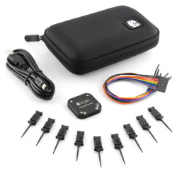
7) Own a logic analyzer. I wasted about 8 hours of painful troubleshooting because my IR timing was off. 15 minutes after hooking up my logic analyzer and it was obvious what was wrong and I had a solution in place. I usually do all of my debugging with print statements. This works for much of the time, but for the situations where one is needed (troubleshooting I2C, SPI, or carefully timed procedures like IR transmission) a logic analyzer is worth its weight in platinum. No really, get one. Your sanity will thank me later.
Here's all the files:
- Illumitune master plan, source file
- Main Board schematic, source files
- Main Board firmware
- IR Controller Board schematic, source files
- IR Controller Board firmware
- IR Detector Breakout Board schematic, source files
- Light Controller Board schematic, source files
- Light Controller Board firmware
When I was first presented with 'making Illumitune work', I began by carefully inspecting the unit. If it's not obvious, Illumitune is an exhibit that plays music and illuminates lights when an infrared beam is broken. Think of it as an IR based harp. It took me a few days to figure out how the original system was designed to work. Slowly pulling apart the system, I found the 'main' board was a PIC 16F628. The date code is 0131 - meaning it was made the 31st week of 2001. Yikes this is old! The 'IR' board is a PIC 16F59 with date code from the 48th week in 2004. While the Illumitune could have been built any time after 2004, it was probably installed around 2005. I don't have any access to the original creator or the original source code so I decided to start from scratch.
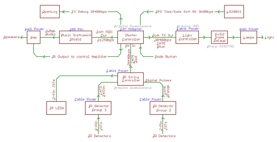
Here are the basic blocks:
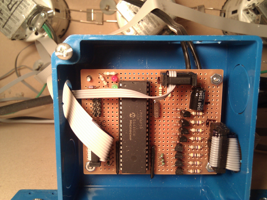
1) This board is located within the top of Illumitune above the halogen lamps (seen in the background) and IR LEDs. It was responsible for turning on/off the IR LEDs and controlling halogen lamps. There are 8 infrared LEDs on the top on the unit and 8 IR receivers built into the base of the exhibit. When these IR beams are broken, the system plays a note and turns on the appropriate light. I assume this is how it originally worked but I never saw it functional.
2) The lights are halogen lamps (seen in the background) and are driven by 110V AC. Fun! This control board has 8 solid state relays (SSRs) with a 10-pin IDC control ribbon. 2 wires are for ground, 8 wires control one light each via TTL level logic.
3) The 'main' board was located on the left side behind a panel. It was sitting on top the MIDI synthesizer and the large amplifier. It is connected to the 8 IR detectors as well as the larger IR board. There's far too many unlabeled pins, buttons, and trimpots to try to figure out what's going on. Easier to start from scratch...

4) The music is generated by a large MIDI synthesizer, which was in turn attached to an amplifier (seen sitting underneath) to boost the volume.
After pulling apart the system, I then set out the replace each piece.
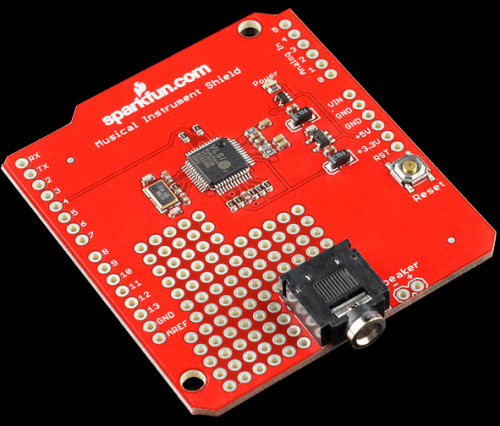
Step 1: Get music working. This was my first project using MIDI. I had learned that the VS1053 could do MIDI synthesis so I did some experimenting with the VS1053 breakout board. Then I sat down and designed the Musical Instrument Shield specifically for this project. This allowed me to completely remove the large and expensive "SoundEngine Music Module" that was previously in the system and had no documentation of its own. The Musical Instrument shield is simple - it receives serial commands from the Arduino ATmega328 and outputs musical sounds, even polyphonic notes and various sound effects.
Step 2: Get IR beams working. This was also my first project using IR. Initially I thought I could turn on LED-4 and then check IR-Receiver-4 to see if the beam was viewable or not. If the LED was not seen then the beam is broken and we should play a note. The problem with this is the IR detectors have a demodulator built in. This means that unless the LED is blinking at ~38kHz, the receiver will not detect the LED is on. This is great for protecting TVs and stereo systems from IR noise, but makes the Illumitune a bit more complex.
So we need to blink the IR LEDs at 38kHz. This was a simple concept that I screwed up badly.
Lesson 1: IR LEDs have a maximum current of 50mA. This is much more than normal LEDs that have a max of 20mA. This means that if you want to drive them at their max (and I did), you can't drive them directly from the microcontroller (most microcontrollers have a max of about 20mA output current per pin). You have to use a NPN transistor to turn them on/off. This is not a huge barrier but it originally caused issues because my IR beams were very weak.
Lesson 2: Timing is everything. I quickly threw together some code to pulse the (weak) IR LEDs. I used the Arduino delayMicrosecond() routine along with some if statements to check each of the 8 channels. I assumed my IR LEDs were turning on/off at the correct rate. I then tore my hair out for a couple weeks while I tweaked the code and hardware in Illumitune. When channels 1 through 4 would work, channel 6 would go completely haywire. And when I changed bits of code to get channel 6 to work, channel 3 would start to have 'phantom' actuation. It was maddening. Finally, I sat down and inspected the IR LEDs and IR detectors with a logic analyzer. What I found was that the LEDs had some really awful timing:
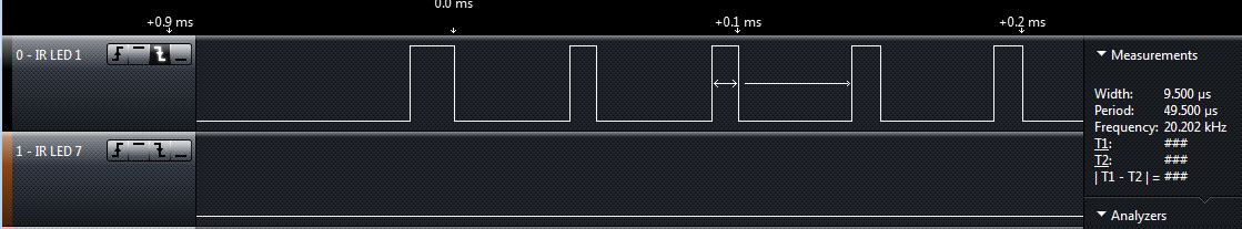
This is channel 1, turning on/off at 20kHz.
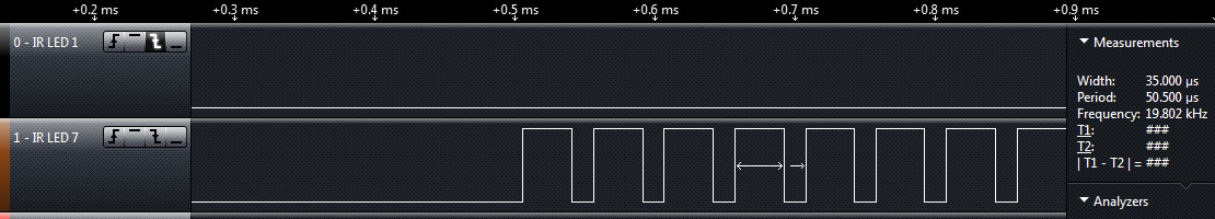
This is channel 7. It too is blinking at 20kHz but note the on time is 3 times as long as channel 1! What in the world? Here's the thing - IR receivers/detectors have many filters built into them. They filter out all light that is not infrared. They also demodulate or 'look for' a signal that is coming in at a certain frequency. The IR receivers I was using are 38kHz receivers meaning all signals that don't pulse at 38kHz it will ignore. The light I was sending was 20kHz. This was obviously really bad.
What was happening is that I was depending too heavily on Arduino's delayMicroseconds() and on the switch timing of my code. Different channels (channel 6 for example) would take a few extra instruction cycles to get to the point where it would turn on LED 6. Once I saw the LED timing on the logic analyzer I quickly re-wrote the code using switch statements and __asm__("nop\n\t"); (also known as no-ops or nops) to really tweak and trim the timing for the LED pulsing to get exactly 38kHz. All 8 channels now had deterministic code which lead to the same timing for each channel.
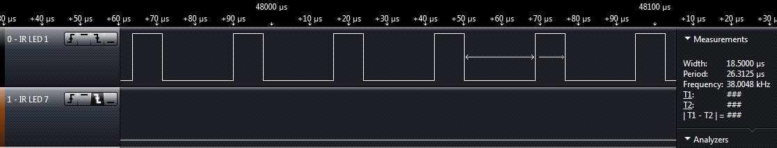
Here is the new and improved timing. All channels now look identical, operate at nearly perfect 38kHz, and the code mimics the RC-5 standard of 32 'ticks'. The IR receivers now respond much more predictably and the IR beams are much more sensitive.
Lesson 3: IR LEDs are viewable with a cell phone. Something is broken, is it the hardware or the firmware? When in doubt, pull our your cell phone to check the see if the LEDs are working. This is a great sanity check to be sure the system is correctly wired.
With these lessons learned, here is how the final system looks:
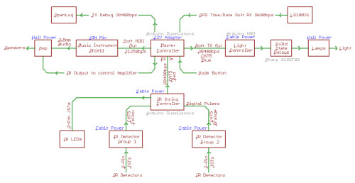
Use Arduinos with shields. Yes, I could have built this entire system on 1 PCB with one microcontroller. The problem is that I knew I was going to have a lot of hardware changes as I learned. It would be cheaper and easier to revise a shield PCB than it would to build up a monster board multiple times. Remember, maintainability is one of the highest priorities. A custom board with a specialty micro requires maintenance done by only the creator. There are a significant number of people in this world who can read a schematic and troubleshoot Arduino code.
By splitting the boards up the project was a much easier problem to attack. For example, creating a board that did nothing but light control has a clearly defined set of requirements. Having independent boards also aids in debugging: it's easy to tell if each piece of the system is alive and working.
IR Controller Board is responsible for turning on 8 LEDs and monitoring the 8 receivers. This would take up nearly all of the GPIOs on the Arduino. This board would constantly be scanning the IR beams and would report any beam breaks over serial to the main board.
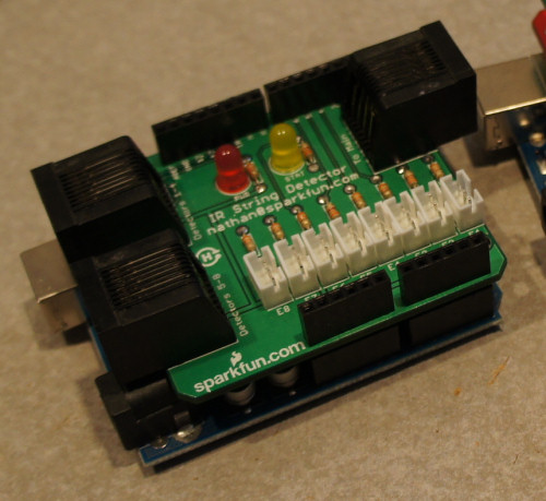
IR Detector Breakout Board is a small board that interfaces the 3-pin JST connectors of the IR detector and converts it to an RJ45 connector so that we can send the signals back to the IR Controller Board.
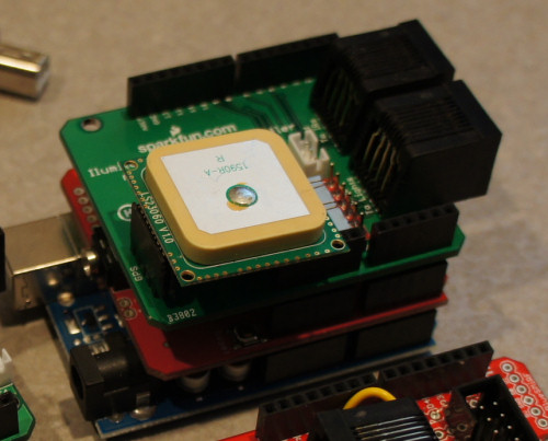
Main Controller Board is responsible for receiving beam breaks, playing notes, and sending light commands to the Light Controller Board. The main board also has an OpenLog attached. This served as a troubleshooting logger - if the exhibit broke, I can re-create how it failed by viewing the logs. I also really wanted to see how much use the Illumitune received by the kids and what parts of the day saw the most usage. If I have a datalogger then I need the correct date and time stamp for the records so I also attached a LS20031 GPS module. Overkill I know, but RTCs require too much babysitting - you have to program the thing, make sure it has battery backup (Illumitune is turned off every night), and any RTC will have accuracy issues. GPS doesn't have any of these problems and I was confident we could get at least a few satellites indoors (in fact it gets 7 satellites and a full location lock!). The main board also reads the status of a basic button. When pressed, the instrument bank changes.
Light Controller Board is responsible for controlling the halogen lamps. It receives serial commands from the main board, turns on a lamp, and then after a short amount of time (250ms) it turns off the lamp.
Rewiring Illumitunes was straightforward. I spent a few days cutting out the old wiring and installing the new. It was a tremendous amount of work re-terminating 8 LEDs and 8 IR detectors but once all the parts were terminated with new connectors it was quite fun to quickly snap in all the new hardware. I used tons of 3-pin JST assemblies. These simple, small connectors made it possible to easily attach or detach the IR LEDs and IR detectors to the various control PCBs. Did I mention I love RJ45 cable? The entire system uses color coded RJ45 cables. The RJ45 connector made plugging the system together extremely easy.
A cordless soldering iron can save you a lot of time as well. I spent a fair amount of time on a ladder working on the top of Illumitune. Plenty of heat shrink and a heat gun are now part of my standard set of tools as well.
Once the new hardware and wiring was installed I had a few more days of hammering on various bugs. After 3 months of work Illumitune started to make sound again! There are still a few small bugs to work out but in general the system works great! I look forward to checking the system and reviewing the logs over the coming months.
I hope these lessons help you with your next project.
I just stumbled upon this tutorial. Nice write-up! I want to thank you for it, because it just helped me out. I've been working on a project, which has fallen to the back burner, primarily due to analysis paralysis. I was trying to come up with one large board that could do everything for the project, but kept getting hung up on the details: how many optically isolated inputs do I need? How many outputs? How many analog inputs? What other special I/O will I need? My plan is to make several of these systems, and distribute them in various locations, all collecting data and controlling equipment and reporting back to a central location.
Well, the problem was that different locations needed different combinations of I/O, and the board was quickly growing out of hand: one location needed lots of inputs, another needed lots of outputs, another needed more analog, etc. No location needed the maximum amount of everything, so there would be plenty of wasted resources if everything was on one big board.
First lesson learned from this post? Use a stack of simpler shields. Therefore, only the required functions are installed at any one location, with minimal wasted resources. One place needs extra inputs? Stack a second addressable shield onto it. Another place doesn't need analog inputs? Don't add the analog shield.
Next lesson? Use polarized connectors. At one point, I was going to put a row of screw terminals along one edge of the board. What a pain that would've been to replace the board if (no, WHEN!) needed.
I appreciate several other lessons learned from this write-up, but I don't think I have to list them all. Just know that I appreciate the post, and will take it to heart! My project is back on track. Thank you!
Nice write-up! I've been doing stuff like this for over ten years, and even I learned a thing or two, and/or you presented your lessons-learned better than I might have. You are more than half-way to creating an entire course on how to build reliable, maintainable installations for museums and elsewhere. (I know this is about a year old; did you create a course, perchance?)
Wow, this is a great tutorial. I especially liked the way you explain how to look at the initial problem and the pointers on how to keep all of the individual parts organized. Very nice!
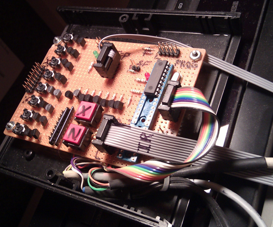
Nate, How are you attaching the LS20031 GPS module (http://www.sparkfun.com/products/8975) to the GPS Shield (http://www.sparkfun.com/products/10710)? OR what is the LS20031 GPS Module sitting on?
It looks like you have it sitting on a some type of sheild (this is the one I am wanting to know what it is), which is sitting on your Musical Instrument Shield, which is sitting on an Arduino board.
Good question. I was about to order one of the LS20031 and would also like to know what that shield is that you're using to interface. It doesn't look like the standard GPS shield, but it does say "Illumi..." on it, and there is an "Illumitunes Light Controller" shield so I'm guessing it's another one-off that should be cleaned up and put in the store =)
Edit: Judging by the schematics further back in the article, it is the elusive "Illumitunes Master Controller".
Good suggestion. Tubes (or recessing the IR receivers down inside the holder 1") would help prevent channel 5 LED from being seen by channel 6 receiver. However, because the receivers have a 38kHz demodulator built into them I still have to blink all the LEDs at 38kHz.
Now THAT is a very valid reason. :) And since you likely needed the microcontroller anyway to do the appropriate switching, you may as well generate the 38KHz signal in the micro as well and save hardware. You have out-reasoned my arguments! :)
Hello,
The Saleae Logic analyser saves my life about 2 times a day on average ;)
When I want a particular timing, I don't even bother calculating the needed instructions with regard to the clock frequency, etc. Just put a guess, get it analyzed, correct it (new guess = desired time / seen time * old guess), and voilà.
Thomas.
I think you did a great injustice to a man creative work; thats just not right. Not everyone has a warehouse full of the newest electronics components; nor should the museums tour guide be poking around inside an electronics box. I also find that scenario highly unlikely, and if it were to happen I think their employer would let them go for fundamental lack of basic judgment calls.
You chopped up this persons creation then went one step further to deteriorate them in public. Maybe you should have made use of all that test equipment and engineers you have instead you essentially defaced a museum piece by covering it with a Sparks Fun logo.
Since you don't recommend the use of custom cables I guess you will be discontinuing a ton of items and converting your stock over to ready made; you can send me old inventory. By the way what unit of measure are you going to be using for increments in cable length?
I mean come on Sparks Fun Engineers can't be bothered with making their own cables! Due to the fact they may be poorly crimped, faulty, misaligned and it just takes too much time. I'm sorry that was just the icing on the cake. I officially challenge you or your best staff to a crimp off in public. I'll show you what quality connections look like and how experience builds speed.
Frustum length wires keep projects neat and organized, sounds like you need to check out some tutorials and set aside some serious practice time. I also think you owe the creator an apology; and hope you saved all the original materials in case you possible altered any function irreparably.
To sum things up would I have used different connections and design principals if I were the creator? Yes. Would I trash talk and belittle the person responsible for a creation which apparently is important to many people. No! Nor would I make it my own if I were given the privilege to service such a creation .
What one thing would I possibly change about the setup if possible? Lighting that had an equivalent spectrum temperature and lumen output, that is not such a watt sucking, heat pumping bulb as halogen. Nathan I was under the impression that If you had either an electronics engineering degree or a field closely related; at the very least staff and consultants.
If you can't handle controlling 110 AC don't complain about it call in a licensed processional; maybe your should re-think selling 110 home automation break our boards until you and your staff become more familiar with them.
I'm glad you feel “Critical comments rock!” so I don't feel bad pointing out the truth, but once again please do not be so disrespectful to the Illumitune's creator. It's un-profesional, out of line and it is something I would not expect to come from a person in your position. I am a female working in a male dominated field and let me also add it's highly unattractive. That is why I married a man outside of the field and he has taught me how to be a better professional more then he will ever take credit for.
Mark's Wife Cynthia
Hi Cynthia - Thanks for such a genuine critique. I did not intend to come across as demeaning to the original creator. Illumitune continues to be one of the most popular exhibits at the kid's museum and I had nothing to do with the original idea, I only volunteer to maintain it. I have held onto the original parts and I would be honored to meet the creator/builder from OMSI (where Illumitune was born) and give them proper gratitude but I can't find any info about them.
I stand by the original tutorial and the lessons I hope to share with other builders. We've seen a wonderful explosion of new people in the field of electronics and interactive art in recent years. But I am saddened when pieces break and they aren't maintained because of poor planning and documentation up front. This tutorial has helped quite a few people. I hope you get some value from it some day.
I like this project aside from the part where you replace a top-line synth module with a bleep chip. What are you doing with the synth module? Are you interested in selling it?
http://www.matrixsynth.com/2010/12/e-mu-sound-engine-midi-synth-module.html
I really enjoyed your story, but like many, my first question was why you didn't just use a 38KHz clock signal for the LEDs. The "shadowing" explainded it clearly. Then I thought, why dont you use that, then scan the LEDs and detectors, like LED1on, read detector1, LED1off, LED2on... maybe at 100Hz or whatever, using the output to drive the gates of NPNs to pull the cathode of each LED low, one at a time, while the 38KHz drives the anode? I'm sure there's a reason, and I have a lot to learn.
You've got a start on some great ideas. There's a bunch of different ways to tackle the problem. I'm a microcontroller+firmware guy who tackles all things with printf debugging. If you know how to rig up more of a hardware solution, go for it.
The man has got skills
Great tutorial! Will the custom boards (IR string detector, light controller) be sold on the site?
Good question - I had not planned on it, but I will check with engineering group and see if they think it's cool enough.
You know you just got put on the speed dial of everyone who works at that museum as "Free IT wizard", don't you Nate?
Hah! I hope not. I don't know much IT ;)
Hey Nate, this is an awesome walk through. Can you recommend clear example code/wiring diagrams for a beginner (that would be me) to get the Musical Instrument Shield up and running?
The Friday Product Post from April 8th 2011 was an great example of the direction I'd like to go. But there seem to be a few more steps when programing with this shield when compared to the simple projects I've created with just my duemilanove.
I'm jumping in using the example code on the product page as well as parsing the code you have shared from this cool project:) Any additional help is very much appreciated.
Cool project. Some thoughts:
It seems you'd have had better luck with the IRLEDs using PWM control for the output. If for some reason the clock speed changes in the future, the existing code is invalid. I ran across this IR remote control package for the Arduino a few months back: IR remote library
I imagine you were trying to stick with stuff that SFE carries, but there are plenty of alternatives out there to the 38KHz sensor for remote control applications. PIR sensors and even active ones, though the cost might have subsequently gone up in that case. I haven't priced such sensors but I imagine they're modular rather than discrete.
I'm impressed to note that I'm not the only one who draws block-diagram documentation using the Eagle schematic editor :D
Hah! You caught that, did you? :) How sad is it that I use Eagle for wiring diagrams. Whatever gets the job done, right?
Great post! About half of the links to products ended up in my wish list and I can't wait to get my hands on them :-). I love the way you guys share what you learn. Keep up the great work!
Nice job -- thanks for the writeup!
For the 38kHz, I'd have been tempted to make a single 38kHz generator (maybe a PIC12F683 controlled by a 50ppm TTL oscillator), and use an AND gate on each LED. That way, you could send logic levels to the AND gates and get either zero or 38kHz out for each one, without worrying about keeping the code length deterministic for each LED. (I've done more than enough counting of clock cycles in PIC assembly; there are a lot more fun aspects to spend time on.)
Great project, must have been fun!
Regarding the timing problems (I think someone said something similar, but let me re-iterate...)
"Use Hardware Timers!"
It is really amazing what kind of timing magic you can do when you delve a little bit into the timers and their operating modes (and maybe also timer interrupts). You'll get dead accurate edges with basically zero jitter, and there's no risk that a small change in the code will stuff up the timing again. Two examples:
- A few years back I implemented a longwave radio transmitter - the modulated carrier was produced "in software", but mainly using HW timers. I programmed one timer to the 120 kHz carrier. A second timer for the modulation used the output pin of the first timer as the clock input, so they always were perfectly synced. The second timer was set to run over with 8192 Hz (the bit rate). I set up a timer interrupt at overflow, which would get the next bit to be sent, and programmed the timer register to either "set at next overflow" or "clear at next overflow" depending on the data bit. As the switching of the output pin was done in hardware, it was dead accurate, perfectly synced to the carrier, and no jitter at all. And the "main" of my program was basically empty, other than a call to "initialise" to set everything up.
- recently I wrote a program to sample audio from the ADC for the Atmel XMega, which also has a HW event system. A timer was set to the sampling rate, and programmed to create an event at overflow (different than interrupt - events don't affect the CPU). The ADC was set up to trigger on the timer event and take a sample. The DMA copied the sample to RAM, and when the buffer is full there is a DMA interrupt to start processing the data. This is the only time the CPU would become active - everything else happens "in the background", the CPU can be put to sleep.
My unwritten goal is to have as little as possible in the main loop of any microcontroller code I write... :)
PS: I definitely agree on the logic analyser! (or an oscilloscope, the more channels the better...) :)
At the risk of being accused of being too "old school", I have a stupid question regarding the 38KHz pulsed IR sources. First, unless I don't understand some of the intricacies of the project, it seems that the IR LED's could just be all pulsed continuouly at 38KHz, all driven from the same 38KHz clock. Was there some reason you used a micro for this and switched each IR LED individually? You are looking for the break beam on the detectors. I have used these detectors many times before, and they work great--if all you need is an on/off signal, I just feed the IR source from a 38KHz clock, derived from a crystal for long term stability, and using a simple clock oscillator. No micro required. :) Also, I am a GREAT fan of pilot lights--Blikey's forever! I usually run an LED to any of these infrared detectors, so I can interrupt the beam and look at the appropriate LED to turn on and off. One other note, the solid state relays are great as long as they work, but in my experience, they get zapped by line glitches and surges fairly easily. they make the plug in style of these, so no soldering required to replace them. This is also another plug for status LED's--you have them fed from the control signal to the solid state relay, so you can easily troubleshoot which direction you need to go. A jumper to bypass the relay to be able to test the power to the load and the load itself (the halogen in this case) also helps in troubleshooting. Note these are not critisisms of what you did or how--you did a fantastic job of "doing it right" for those who follow. These are just a few things I have learned myself from working and designing these kinds of toys. :) Kudos to you for the time, money and effort you put in to help a very worthy cause!
Good question. If I blink one LED, up to 4 receivers may 'see' that LED blinking. Each IR LED blinks in a beam and that beam expands to probably 24-30" at 8 feet. So if the IR receivers are 6" apart, they will 'see' cross talk from the wrong LEDs. That's why we needed to turn on/off the LEDs at certain times and ignore certain receivers when the IRs were blinking.
what difference does it make if the beam has spread across multiple IR rx's by the time it's xx ft away? Aren't you just trying to interrupt the beam to a specific IR rx. with a hand to indicate a plucked string? Who cares where the beam came from?
Because you could get IR shadows on the wrong sensor, making the Arduino think the wrong sensor is being tripped. Plus there all that blah blah stuff I said about having to use more power if all the LEDs are on. I think...
If I understand things right- IF you were to run all the LEDs at the same time, it would take more power to run all of them, then if you DeMUX (74LS154 or the equivalent- AKA your microcontroller) one LED at a time which would uses less power. Just one of the lesson I leaned back in the TTL days from a friendly Engineer, when I was in high school.
{Come to think about that... You could have used the 74HC154(http://www.nxp.com/documents/datasheet/74HCHCT154.pdf) to select one of the 0 through 15 LEDs, using the G1 or G2 to modulate you're 38KHz signal through to your 0-15 LEDs. Part of the reason for doing this is you only need one source for your 38KHz, and only 4 data lines to select which LEDs you want to turn on. You would still have to had some type of Darlington Transistor to control the power for your LEDs. If I remember right Sparkfun has a Darlington Driver 8-Channel ULN2803 DIP package (http://www.sparkfun.com/products/312) that's an inverter that could be used as a drain for the current for the LEDs. }
I'm also just surprised that you did not get rid of the 110VAC halogen lights in favor of cooler running Luxeon Rebel High Power LEDs that Spark Fun has. Which would mean less power/heat, and you could get rid of all the 110VAC power except for the power supply, and no more worried about 110VAC power spikes. Then all you would needed to run things is a N-Channel MOSFET (http://www.sparkfun.com/products/10213) or the Darlington Driver 8-Channel ULN2803 DIP package. I am surprised that there is not a I2C Blink controller for the Luxeon's LEDs that you could used. Also If you had used the RGB version you could make any color for any of the harp strings, which could have been reflective of the octave or sound that's being played, or make the LED's do a color chase to grab attention to the display/instrument.
Apologies in advance for a critical comment.
Did you work out what was wrong with the original hardware? Surely the prime suspects for the fault are a dry solder joint or perhaps a failed power supply cap, which could be tracked down and fixed quickly and cheaply.
It looks like there is also rather a lot more that could go wrong with the new design than there was with the old... especially if the next person who opens it up to maintain it sees the RJ45 cables and assumes he can debug it by plugging one into an ethernet port.
Critical comments rock!
Each person must make their own decision to repair or replace. Initial plug/unplug and power cycling did not work. Past that level of trouble shooting, the gremlin list (clock skew, flash corruption, cold solder, cable failure, power problems, dust on the IR sensors, etc) and lack of documentation made the project not worth probing and poking for any length of time.
I guess that's the point of this tutorial - had there been adequate accessible documentation, we would have a higher chance of successful repair. Without documentation, any project runs the risk of becoming unmaintainable.
So many projects like the Illumitune evolve as they're repaired and upgraded. After a while, kludges pile up and you've got a system that is simply unmanageable. If nothing else, technology moves so quickly that what was once an elegant design becomes a convoluted nightmare. What used to take a board full of components might be just a couple of chips.
Rebuilding from scratch is often the simplest and most robust solution.
The person to assume that is clearly not reading the labels printed by the $30 label printer ;)
I, too, am curious as to what might have been wrong with the original hardware - but clearly it could be just about anything; yes, it could have been a solder joint.. but what if it was the synthesizer module? How do you go about fixing that if it's some potted chip that decided to kick the bucket?
Replacing the system was definitely the way to go. Even if some of the choices seem overkill, perhaps they'll allow a more future-proof exhibit.
At the same time, I question the use of the IR receivers with built-in filters. This makes sense in an environment where you might expect IR noise. But in the case of this exhibit, that seems rather unlikely. Cheaper IR receivers could then be used and have saved quite a bit of headache.
Rant about not replacing the halogen goes here - running out of posting space ;)
I understand that the filtering IR is less susceptible to interference (like daylight).
Correct - but that didn't apply here; though I guess if they ever relocate the exhibit near a window or some other stray IR source, they'll be glad to have the filtering type :)
If it was just the MIDI module that was broken, it could be replaced with a Sparkfun VS1053 breakout board ($24.95).
I've seen other projects using RJ45 connectors with big "NOT ETHERNET" labels just to head off that sort of mistake.
Misspelled the word rebuilding in the beginning. :) Great project!
Thanks! Good point - fixed.
Very nicely done, and documented! I have impressed many by proving to them that I can see their TV remote (or laser tag gun) light by using my cell phone camera/digital camera/ or camcorder.
While I personally think there was over kill in some areas, I wouldn't think to second guess your hardware design as there are 1001 ways to get from point A to point B. Documentationwise for the "next guy", is there a USB terminal program that can read your diagnostic output stream; the way hyperterm can read rs232? How about a scope of the task doc. that explains what it supposed to do for the next guy to read when its dead as a door nail. Something like:(8 ch., each consisting of an always on 38Khz IR emitter at top and a matching IR rx. at bottom. Also matching color halogen light top and bottom. Sequence thru each channel. When IR beam is broken that channel's top and bottom light flash off temporarily via interruption of 110vac using SSR, and a tone is generated for xx time. Multiple scales / instruments for all ch. can be selected by single push button selector switch. Tones and instruments, SSR's and IR rx. via uController. See schematic )
That's a fine job, Nate. Thanks for documenting it.
I've been doing work like this for a long time, but I still got a few good ideas and learned a few things. Thanks again!
Wow. That's really awesome work! Did the museum give you the $300+ dollars in parts needed to redo this? Or, did Sparkfun donate the parts?
Many people and museums just don't have the kind of money it takes do a system the way Nate has done.
I volunteered the time and donated the parts. It's not cheap but worth it to watch the kids play.
And I'll bet you even had a little fun doing it! :)
Ya, just a little bit ;)
Any clues on the original system failure? Perhaps, overheating or a single loose connection?
Great project report!
Great idea. I'm sure to make use of a gps unit as a RTC in the future :)
Thanks
The only clues I have:
The system made some noise (of the musical type). This would indicate the MIDI box was still working.
Boards were blinking and had ~5V on the boards.
Past that it would have required probing with a o-scope on the top of a ladder to try to decrypt what signals where being passed back and forth. Perhaps I folded too early - I will admit I like designing and laying out new boards.
Did you ever figure out why it broke?
Although sometimes frustrating, I actually have a lot of fun figuring out why something broke. I usually learn something at the same time.
A lot of the time, the builder may not be able to imagine all of the 1000's of ways their product will be abused. (Especially when kids are involved.) Figuring out "what went wrong" gives you better data on how to prevent a failure later, or in another project.
I'm wondering why you didn't use the tone() function to generate the 38kHz signal. Was it because you didn't want a 50% duty cycle? If that's the case, why was a 50% duty cycle not used?
This is a great project and it is amazing that you posted so much information and your entire design process. Thanks for the code too, it really helps us beginning DIYers gain a lot of insight into more complex projects. Thanks so much. Don't worry I'll honor the beerware licensing agreement if I use it.
I would suggest using a hardware pwm and a mux ic considering you only need one at a time
Same pins could be used for another mux ic for the receivers
Something like the 4067 breakout you have would be perfect
A good idea! I did not think to try the tone() function. It should/might work. I worry that the 50% duty cycle may not be ideal for the NEC codes I was trying to pass. But then again, initially I was passing very badly timed signals (20kHz instead of 38kHz) and the IR receivers did a pretty good job of cleaning up the signal.
Please do use/learn from my mistakes. Let me know if any of the code leads you astray and I'll clean up the confusing parts.
I would have made a single 38kHz source, and used it to drive a transistor below the LED switching transistors. Then you could apply the 38kHz signal to any LED by simply turning on its transistor.
Haha, saw a blue flame at the end trying to celabrate bungie day!
I was actually hoping no one would notice :) This was my first video editing project and I didn't have the nice pure white logo that Gregg (our video pro here at SparkFun responsible for all our awesome videos), so I simply inverted our regular logo to get white and fancy blue. Good eyes!
Sparkfun customers are the most observant customers.