
Mr. Roboto Quickstart Guide
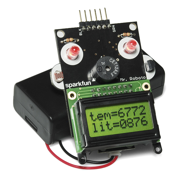
Class is in session! Mr. Roboto has arrived to help you hone both your soldering and programming skills. Coming to you just half assembled, Mr. Roboto will first need your help putting his LED eyes, buzzer nose, LCD mouth and sensor ears into the right spots. Once assembled, you'll be able to use Mr. Roboto to explore microcontroller programming using the cozy, super-popular Arduino IDE.
In this tutorial I'll cover everything you need – from assembly to programming – to turn the bags of miscellaneous Mr. Roboto parts into a fully functional robotic face. So whip out your soldering iron, and get your programming fingers ready.
Requirements
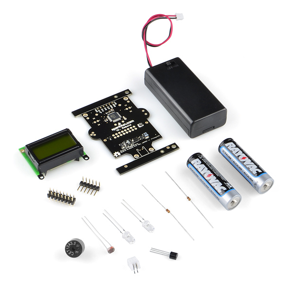
Well, obviously, you'll need a Mr. Roboto kit, which includes:
- Mr. Roboto PCB with Surface-Mount Components
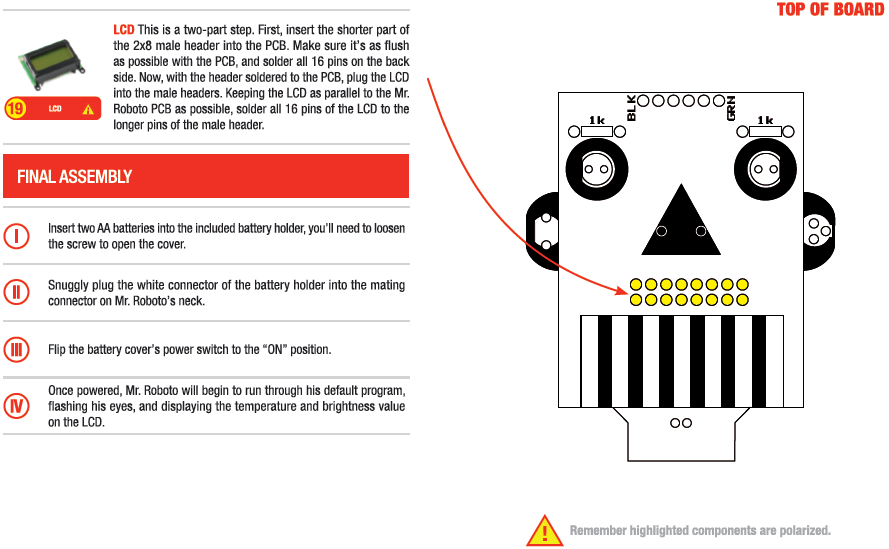
- 1x Mini LCD Screen
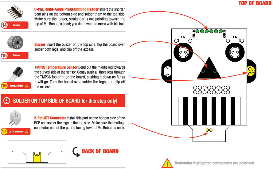
- 1x 6-Pin Right-Angle Header
- 1x 16-Pin Straight Header
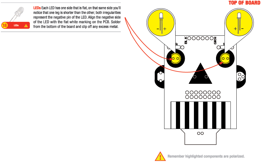
- 2x Super Bright Red LEDs
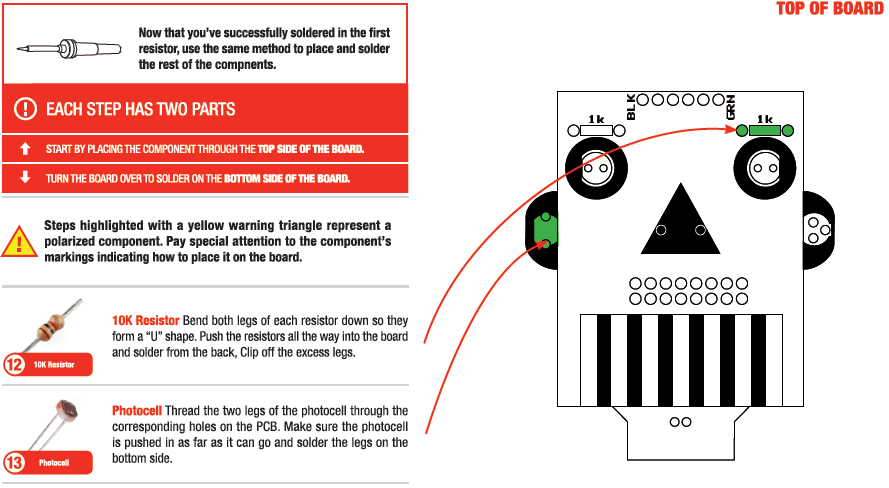
- 2x 1kOhm Resistors
- 1x Miniature Photocell
- 1x TMP36 Temperature Sensor
- 1x Piezo Buzzer
- 1x 2-Pin JST Connector
- 2x AA Batteries
- 1x AA Battery Holder with Power Switch
What else do you need? At a minimum, the required tools for assembly are a couple opposable digits, a really basic soldering iron, a bit of solder and some cutters. You'll also find a small phillips-head screw driver to be very handy. In addition to those tools, other items you might find helpful include needle nose pliers, and perhaps a third hand, or vise, to keep everything nice and stable.

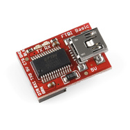
That'll cover everything on the assembly side. Once he's built you'll need something to connect Mr. Roboto to your computer. Either an FTDI Basic Breakout, or FTDI Cable would be my recommendations for that job.
Finally, on the software side of things, you'll need a computer (Mac, Windows, or Linux) with the Arduino software installed on it. You can download the latest version from here, make sure you pick the version that best suits your OS. Windows users will download a .zip file, which you can unzip to any directory you find convenient; from there double click Arduino.exe. Mac users should just be able to double click the download to launch the environment.

What It Does
Mr. Robot's main purpose is to educate. We want to make you both a professional through-hole solderer, and we want the assembled kit to be a fun way for you to explore Arduino programming.
Mr. Roboto has three different kinds of outputs (LEDs, buzzer, and LCD), and two inputs (photocell and temperature sensor). The kit's healthy mix of components should lead to a variety of electronics/Arduino topics to discover, including:
- Soldering through-hole components
- How to read a schematic
- Installing and using the Arduino IDE
- The basics of every Arduino sketch
- Digital output
- Analog output (Pulse-width modulation)
- Analog input
- Serial input and output
- Installing and using Arduino libraries
How To Use It
Assembly
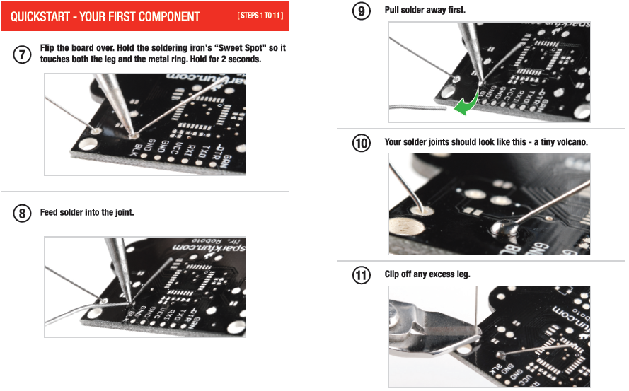
Assembly of the Mr. Roboto Kit requires soldering. Soldering all the parts to the PCB will form a nice, solid, electrical connection. If you've never soldered before, don't fret! Because everything is through-hole this is one of our easier soldering kits. But, if this is your first time, I'd encourage you to take a quick detour over to one of our excellent soldering tutorials.
The kit comes with some stylish assembly instructions (thanks SparkFun Marcomm department!). And, really, those are better than anything I could whip up in MSPaint, so I'm just going to regurgitate those instructions. Follow these step-by-step instructions, and you should be golden. Click any picture below to make it larger.

Mr. Roboto can run off a couple AA batteries (using the included battery holder), or via your FTDI Basic Breakout. However, take care to only use one power source at a time. Connecting both batteries and an FTDI to Mr. Roboto at the same time can confuse him, and, more importantly, damage the FTDI board.
First, try powering Mr. Roboto off batteries. Load up the battery holder with the included AA batteries. You'll have to find a small phillips-head screwdriver in order to slide the cover off. Then plug the battery holder into Mr. Roboto's neck. The mating white connectors are polarized - make sure you line up the notches!
There's an ON/OFF switch on the battery holder, flip it to ON and watch Mr. Roboto do his demo thing!
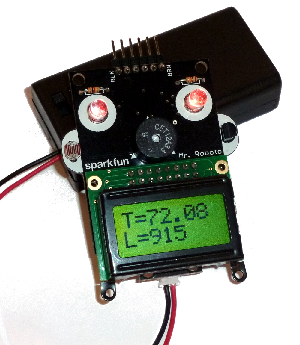
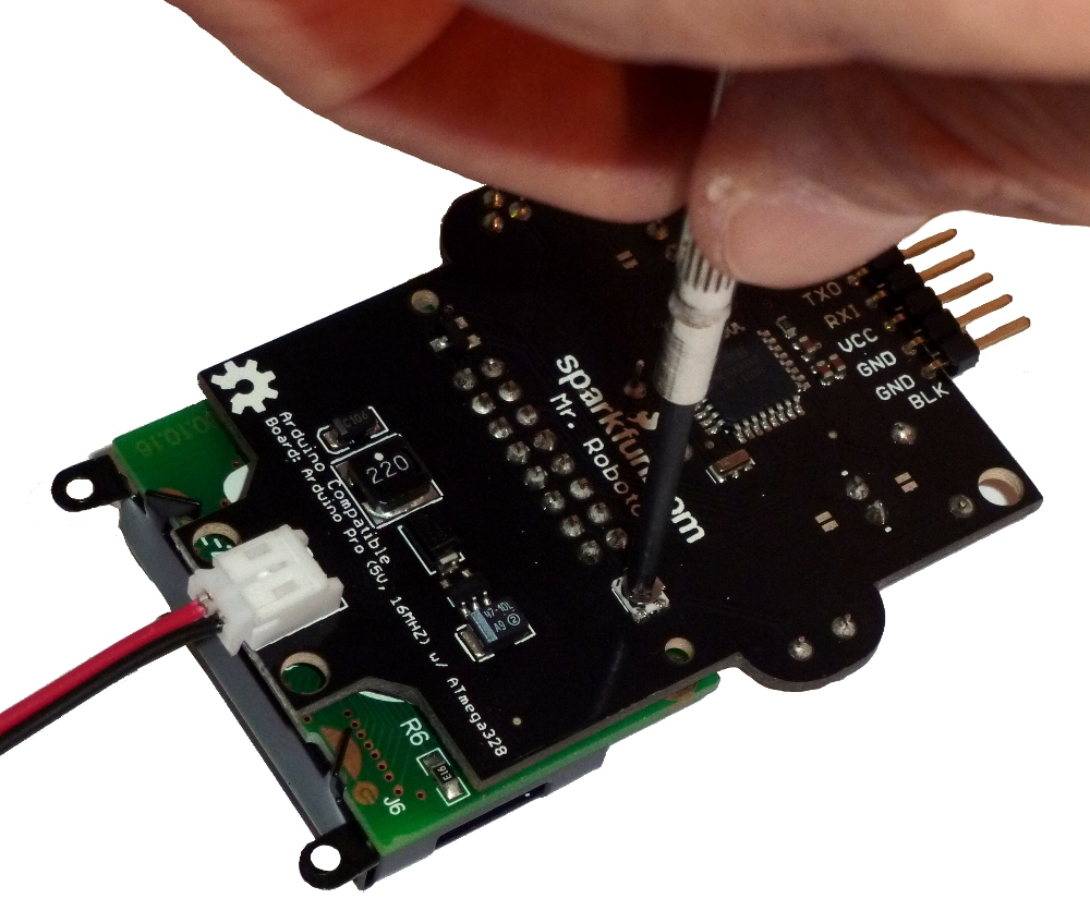
If you don't happen to see any text on the LCD, you may need to adjust the contrast. Find a small phillips screwdriver, and use it to adjust the tiny potentiometer on the back of Mr. Roboto. You shouldn't have to turn too far (definitely don't over-adjust the pot) to make the display visible.
The demo firmware should test everything on Mr. Roboto. If select components of Mr. Roboto's face aren't working, double check their solder joints. If the parts are polarized, make sure you put them in in the correct direction! If the firmware doesn't run at all - no blinky LEDs, no LCD lighting up, no buzz, et. all - make sure the battery switch is ON and the connector is snuggly plugged into Mr. Robot's neck connector. Then move on to checking for shorts (especially between power and ground). If you've still got no luck, try either posting in the comments below, or seeking out further technical assistance.
Once you've tested Mr. Roboto, and verified everything's working (and have gotten tired of seeing him run the demo code), turn the battery holder to the OFF position. It's time to power him off the FTDI board.
Plug in your FTDI board or cable. Windows users note: if this is your first time connecting an FTDI board to your computer, you'll have to install drivers for it. The drivers should be included with the Arduino file you've downloaded. Follow Arduino's installation instructions, specifically those under the Installing drivers for the Arduino Duemilanove, Nano, or Diecimila with Windows7, Vista, or XP heading here.
Now plug the FTDI board/cable into Mr. Roboto's spiky hairdo. You've gotta plug it in the right way though! Take care to match up the BLK and GRN lables (or if you're using a cable, match up the black and green wires with their respective labels).
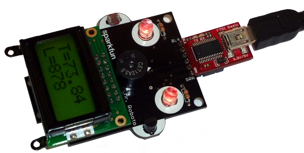
With the FTDI connected, Mr. Roboto should again run his demo code.
Hardware
Embedded systems like Mr. Roboto can be split into two important categories: hardware and firmware. The circuit and the code work hand-in-hand, and you have to have knowledge of both before you can hope to make your Mr. Roboto do anything. So let's go over the hardware part.
It helps to think of Mr. Roboto as a real human head. He's got a brain - that little, 4-sided, surface mount chip - called a microcontroller. That brain is connected to all of Mr. Roboto's peripheral inputs and outputs - everything you just soldered. Each of those components has at least one of it's own connections to the brain, which is called a pin, and is given a specific number to be referenced in code. Here's a table of each of Mr. Roboto's pin number connections:
| Component | Arduino Pin Number(s) |
|---|---|
| Left LED (eye) | 9 |
| Right LED (eye) | 3 |
| Photocell (left ear) | A0 |
| Temperature Sensor (right ear) | A1 |
| Buzzer (nose) | 6 |
| LCD (mouth) | (4, 5, 7, 8, 11, 12, 13) |
If you want an even more detailed look into what's going on inside Mr. Roboto's head, you can peek at the schematic. Click the image below to see the bigger picture (or, rather, PDF).
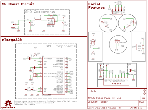
The schematic details every single component on Mr. Roboto - through-hole or surface mount - as red symbols with pins extending outwards. Some components on the symbol are just big boxes (e.g. the ATmega328 processor, LCD, temperature sensor). Other components, like the resistors, capacitors, and diodes, have their own, more standardized symbol. Can you tell which is which?
Wires on the schematic are shown as green lines. Each wire in the schematic has a name, which is represented by a grey, pentagonal shape with a label inside. If wires share a name those two pins are connected on Mr. Roboto's circuit board. For example, the anode of the left LED is connected to D9, which is also connected to the PB1(OC1A) pin on the ATmega328; this represents a connection between the LED and that specific pin on the processor. Can you map each of the connections on the right side of the schematic to pins on the ATmega328? They should match the table above.
Now, with the kit assembled, and knowledge of the circuit, you can finally program Mr. Roboto, and bend his facial features to your will (muahahahahahaha?).
Firmware
Let's dive head first into Mr. Roboto's demo code, which comes programmed on the chip when the kit is shipped. This code should show you how to make use all of Mr. Roboto's components.
Click here to download the Mr. Roboto demo code.
That download also includes a library, which you'll need to install before the code will compile. Libraries are an incredibly powerful part of the Arduino development platform. They're complete, tested pieces of code which make your programming job much, much easier. To install libraries in Arduino, you'll need to put it into a libraries subdirectory of your sketchbook. Sketchbook-a-what-now? By default, your sketchbook will be placed into your My Documents/Arduino/ directory. In this case we're installing the LiquidCrystal440 library, so your library would look like this correctly installed:

With the library correctly installed, open up the Mr_Roboto_Demo.ino file, included with the download above.
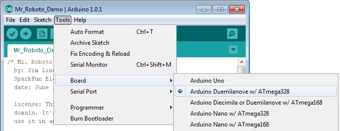
Before you can upload the sketch you need to tell the Arduino environment. First, select your board. Go to the Tools > Board menu and select Arduino Duemilanove w/ ATmega328.
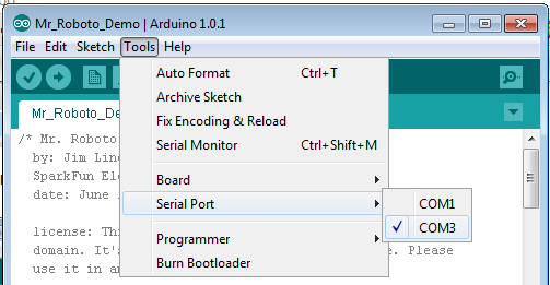
Second, you'll need to select your serial port. Go to Tools > Serial Port, and select the proper port. On Mac, this'll be something like /dev/tty/.usbserial###, on Windows it should be COM#.
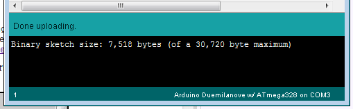
Now click the Upload button - the right-arrow-looking button, second to the left. Then twiddle your fingers for about 10 seconds. The IDE will compile the code, which will take a while, and then it will upload the code, which might take a while as well. Successful code upload should give you a status like this:
If you're getting an error, double-check all of the settings above. Is everything connected properly? Labels between the FTDI and Mr. Roboto matching up? Arduino's got a great troubleshooting section, give that a quick read-through. If you're still stumped, drop a comment below, or contact us for technical assistance.
If the code worked, you should be greeted by a very similar Robot head. Let's dissect the code and figure out how he's doing what he's doing. The first snippet:
/* Mr. Roboto Demo Code
  by: Jim Lindblom
  SparkFun Electronics
  date: June 12, 2012

  license: This code is all released under the public
  domain. It's provided as an educational example. Please
  use it in any way you see fit.

  Mr. Roboto will play a jingle, to warm up. Then he'll tell
  you what temperature and light values he's reading. The
  temperature and light values will be averaged over 50
  readings. He'll also do some crazy eye flickering throughout.

  You'll need the LiquidCrystal440 installed. It should be
  included with this sketch, or you can download it from here:
  http://code.google.com/p/liquidcrystal440/downloads/list
  The library should be installed in the 'libraries' folder of
  your Arduino sketchbook (go to File > Preferences to see
  where that is).
*/

// Here's how we include the LiqyidCrystl400 library:
#include <LiquidCrystal.h>
If you've never seen Arduino code, or any code for that matter, before, this'll be a lot to drop on you. Let's first get comments out of the way. Comments are pieces of code that are completely ignored by the Arduino, they're only there to help you or others understand the code better. Arduino displays comments in gray (or blue in the case of a link). Comments can be defined in one of two ways: A single line comment will be any characters following the double-slash ("//"), the comment ends as soon as the next line begins. A block comment is anything between the "/*" and the "*/" characters. Block comments can span multiple lines.
The snippet of code above is 24 total lines of code, but only one line actually does anything: "#include
The next 47 lines of code look something like this:
/* Eye, nose, and ears pin definitions: */
const int rightEye = 3;  // right eye LED is pin 3
const int leftEye = 9;  // Left eye LED is pin 9
const int nosePin = 6;  // Buzzer nose is pin 6
const int lightPin = A0; // photocell is attached to A0
const int tempPin = A1; // the temperature sensor is attached to A1

/* LCD Pin Definitions: */
const int lcdRSPin = 13;  // Register select pin
const int lcdENPin = 12;  // Enable pin
const int lcdD4Pin = 11;  // Data bus line 4
const int lcdD5Pin = 8;  // Data bus line 5
const int lcdD6Pin = 7;  // Data bus line 6
const int lcdD7Pin = 4;  // Data bus line 7
const int lcdBacklightPin = 5;  // LCD Backlight control pin

/* This counter variable will range between 0 and 511. We'll
   use it to flicker the LED eyes. */
int counter = 0;

/* These variables will all be used in taking the average of the
   light and temperature sensors */
const int readingCount = 50;  // should not excede 64
int index = 0;  // This is the index we use to keep track of the averages
int rawTemperatureReading[readingCount];
long rawTemperatureTotal = 0;
float temperatureC;  // This is where we store temperature in celsius
float temperatureF;  // This is where we store temperature in farenheit
unsigned int rawLightReading[readingCount];
unsigned int rawLightTotal = 0;  // This is where we store the light reading

/* Here are some variables we'll use to make a little jingle at startup
   First we'll define frequencies of a few notes to use in the jingle */
const int NOTE_F4 = 349;  // F4 (F above middle c)
const int NOTE_DS4 = 311;  // D-sharp 4
const int NOTE_REST = 0;  // Rest, no tone
const int jingleLength = 12;  // This is the length of the jingle - 12 notes
/* This array contains the note played, in order */
const int jingleNote[jingleLength] = {
  NOTE_F4, NOTE_F4, NOTE_F4, NOTE_F4, NOTE_F4, NOTE_DS4, NOTE_REST,
  NOTE_F4, NOTE_F4, NOTE_F4, NOTE_F4, NOTE_DS4};
/* jingleDuration contains the length of each note played
   8 = 1/8 note, 4 = 1/4 note, 32 = 1/32 note, etc.*/
const int jingleDuration[jingleLength] = {
  8, 8, 8, 8, 8, 4, 32,// do-mo-ar-i-ga-to-(rest)
  4, 4, 8, 8, 4 };  // mis-ter-ro-bot-o
const int jingleBPM = 60;  // Jingle beats-per-minute = 60 bpm

/* Finally, we need to make an lcd variable. This will tell
   the LiquidCrystal library which pins to use to control
   the LCD. We'll name our lcd...'lcd' */
LiquidCrystal lcd(lcdRSPin, 255, lcdENPin, lcdD4Pin, lcdD5Pin, lcdD6Pin, lcdD7Pin);
Every one of these lines is an example of variable declaration. Variables are a named object which can be referenced or changed throughout the rest of code. A variable can store a number, or a sequence of characters; basically some piece of raw data. As you can tell by the above 47 lines of code, I love variables, and you should too. They're an essential part of coding, because they allow you to manipulate data, and they make reading and writing code much easier (at least well-named variables do).
But I digress...before you can use a variable you have to declare it. If you declare a variable at the top of your sketch it becomes a global variable, which means we can use it anywhere in the rest of our code. Most of the variables in this sketch are global. Local variables, on the other hand, can only be used within the "{" and "}" where they're defined (this is what's known as scope).
To declare a variable you need to give it a type. int is the most common type, we use it for integers - numbers without decimal points. float is used for numbers with decimal points. There are many other types - types for characters (char), very big numbers (long), very small numbers (byte) - but those are the only types we'll really need for this sketch. You'll also see const before some types, this means the variable can never change after it's declared.
The variables in this sketch have a variety of purposes. There are variables for pin numbers, make sure they match up with the schematic and pin-table above. There are variables for sensor readings. Check out the comments for more details on which variable does what.
The next block of code is our setup() function. This is one of the two functions that every Arduino sketch is required to have. setup() runs once, and only once, at the very start of your sketch. It's a great place to put code to initialize variables, or do one-time, top-of-the-code operations.
void setup()
{
  /* Let's set up the pin modes first: */
  pinMode(leftEye, OUTPUT);  // Left eye LED is an output
  pinMode(rightEye, OUTPUT);  // Right eye LED is an output
  pinMode(nosePin, OUTPUT);  // The buzzer nose is an output
  pinMode(lcdBacklightPin, OUTPUT);  // The LCD backlight LED is an output
  pinMode(lightPin, INPUT);  // light sensor is an input
  pinMode(tempPin, INPUT);  // Temperature sensor is an input

  /* Now to initialize the LCD. First tell Mr. Roboto the LCD's dimensions */
  lcd.begin(8, 2);  // Start up the LCD, 8 columns, 2 rows
  analogWrite(lcdBacklightPin, 255);  // Turn the backlight fully on
  /* Now to write a splashscreen message. */
  lcd.setCursor(0, 0);  // Reset the cursor to the top left point
  lcd.print(" Hi I'm ");  // "Hi I'm" on the top row, notice spaces are used to center it
  lcd.print("MrRoboto");  // "MrRoboto", we had to get creative with the name to fit it on one line

  /* While the splash screen displays, let's play a little jingle on
     the nose buzzer, can you recognize the song?
     Attribution for most of this bit of code goes to Tom Igoe. Check out
     his example sketch by going to "File > Examples > 02.Digital > toneMelody" */
  for (int i=0; i<jingleLength; i++)
  { // Run through this for loop once for each note
    /* First lets calculate how long to play the note
       this value will be in miliseconds, so we divide 60000 miliseconds
       by our beats per minute, and divide that by the note's duration */
    int noteDuration = (60000/jingleBPM)/jingleDuration[i];
    /* Now we'll play the tone using the tone(pin, frequency, duration)
       function. The pin will always be nosePin, the note is defined above,
       and we just calculated the duration in milliseconds */
    tone(nosePin, jingleNote[i], noteDuration);
    /* Now just a short delay, so you can distinguish between the notes.
       This calculation is mostly arbitrary, but it sounds good. */
    delay(noteDuration * 1.3);
  }
}
There's certainly a lot going on there. Check the comments for a more detailed, line-by-line explanation.
First we initialize all of the pins we're going to use, by calling the pinMode() function. pinMode() sets a pin as either an INPUT or an OUTPUT. For example, we set the LED eyes as outputs, while we set the temperature and light sensors as inputs.
Next we go on to initialize the LCD. These "lcd...." functions are making use of the LiquidCrystal library you've installed.
After the LCD is initialized, and the splash screen is setup, Mr. Roboto plays a little jingle on his nose. Do you recognize the tune (that question could also be phrased as "Were you born before 1975")? This makes heavy use of the tone() function, which enables you to play any frequency on the buzzer for a specific duration.
And so ends the setup() function. Next we jump into the loop() function, which is the second of our required functions. Aptly named, loop() loops. The function starts at the "{" and it runs through the code until it reaches the matching "}", before it jumps back to the top of the function. loop() is where you'll place the main functionality of your code.
In Mr. Robot's loop() there are three main operations going on. Every time through the loop Mr. Roboto reads both the light and temperature sensors. Those readings are used to calculate a rolling average, to get a more steady, not-so-time-sensitive value. Every 50ms Mr. Roboto will update his LED eyes, they'll slowly blink in and out. Finally, every 500ms (that's twice a second), Mr. Roboto will update the LCD with the light and the temperature averages.
void loop()
{
  /* First we'll get a reading on each analog sensor */
  rawTemperatureReading[index] = analogRead(tempPin);
  rawLightReading[index] = analogRead(lightPin);

  index = index + 1;  // Increment the index by 1
  /* But if index reaches the top of our rolling average window
     set it back to 0 */
  if (index >= readingCount)
    index = 0;

  /* This if statement is just like saying do {this} every 500 ms
     millis() returns the amount of milliseconds that have past
     since the sketch started running. The %, or 'mod', operator
     returns the remainder of millis() divided by 500, and it
     will only equal 0 when millis() is a multiple of 500.  */
  if ((millis()%500) == 0)
  {
    /* First we need to calculate the rolling average of our
       temperature and light readings */
    rawTemperatureTotal = 0;  // reset rawTemperature
    rawLightTotal = 0;  // reset rawLight
    /* Now add up each of our readings into a total value */
    for (int i=0; i<readingCount; i++)
    {
      rawTemperatureTotal += rawTemperatureReading[i];
      rawLightTotal += rawLightReading[i];
    }
    /* And then divide the total value by the number of readings to get
       the average over 'readingCount' number of readings */
    rawTemperatureTotal /= readingCount;
    rawLightTotal /= readingCount;

    /* Lets convert the rawTemperature reading to units we can
       better comprehend.  The TMP36 has an offset voltage of 0.5V
       and then each 10 mV are equal to one degree C. */
    temperatureC = 100.0 * ((rawTemperatureTotal * 5.0 / 1024.0) - 0.5);
    temperatureF = (temperatureC * 9.0 / 5.0) + 32; // This is the standard C-to-F conversion

    /* Now we'll update the display */
    lcd.clear();  // Clear the display
    lcd.setCursor(0, 0);  // set the cursor to top left
    lcd.print("T=");  // Print "T="  (temp = )
    lcd.print(temperatureF);  // print the farenheit temperature
    /* Comment out the line above, and uncomment the line below
       if you want to print the celcius temperature instead */
    //lcd.print(temperatureC);  // print the celsius temperature
    lcd.setCursor(0, 1);  // set the cursor to bottom left
    lcd.print("L=");  // print "L=" (light = )
    lcd.print(rawLightTotal);  // print the brightness reading
  }

  /* In this section of the loop, we'll update the LED eyes.
     Using analogWrite() we fade the LED eyes in and out, they'll
     always be the opposite of eachother.
     This piece of code should run once every 25 milliseconds */
  if ((millis()%25) == 0)
  {
    counter++;  // Increase counter by one
    if (counter >= 512)  // we need counter to stay within the 0-511 range
      counter = 0;  // reset counter if it gets too large
    if (counter <= 255)  // right eye going down, left eye going up
    {
      analogWrite(leftEye, counter);  // outputs 0-255 to left eye
      analogWrite(rightEye, 255-counter);  // outputs 255-0 to right eye
    }
    else if (counter <= 511)  // Right eye up, left eye down
    {
      analogWrite(leftEye, 511-counter);  // outputs 255-0 to left eye
      analogWrite(rightEye, counter-256);  // outputs 0-255 to right eye
    }
  }
}
To read the value of the analog senors, we need to use the analogRead() function. analogRead() returns an integer value between 0 and 1023, which is relative to 0 and 5V. The analog readings are stored in an array, the index of which continues to increment. We'll use that array to calculate a rolling average.
To write to the LEDs, we use the analogWrite() function. To use the analog function, you have to give it a pinNumber (leftEye or rightEye in this case), and you have to give it an analog value between 0 and 255. 0 turns the LED off, and 255 turns it completely on; any other values will be somewhere relatively in between.
There are a host of LCD functions used in the loop():
- lcd.clear() - This function clears the LCD. The backlight remains the same, but all of the characters are erased.
- lcd.setCursor(column, row) - This function requires two parameters - column and row - and it sets the lcd's "cursor" to a set position on the LCD. When you call a print function, the print will start from here. Remember this LCD has 8 columns, so your column variable can be anywhere between 0 and 7. And it has 2 rows, so the row variable can only be 0 or 1. Note that setting the cursor to 0,0 would set it to the top left of the display.
- lcd.print(val) - This is the big kahuna. The print function requires one parameter - something to print. The parameter can be an variable (integer or char), or it can be a defined string of characters (like "Hello"). It'll start printing at the location of the cursor, then it'll keep going until it reaches the end of the string. Note that, if it reaches the bottom-right of the display, it'll go back up to the top-left on the next character.
- It's not actually used in the loop(), but you can also adjust the intensity of the LCD's backlight. Control it just like you would an LED, by using the analogWrite() function, where lcdBacklightPin should be the value of the pin.
So there's the quick run-down of the more important functions and coding conventions used in the sketch. If you're left with any questions, make sure you read the comments in the sketch. Then try consulting Arduino's reference page. They've got a entry for every Arduino function, variable, as well as more general tutorials on code conventions and structure.
I hope this tutorial serves as a great starting point for your Mr. Roboto kit. There's so much more I could write, this tutorial is already ginormous. If you're looking for more stuff to learn I'd encourage you to check out the examples included with Arduino (File > Examples > ...). These examples in particular:
- Blink (!) - This is the most basic of examples, but it touches on one of the most important functions, which wasn't covered in this tutorial - digitalWrite(). It's like analogWrite(), but with only two possible values - HIGH or LOW - and nothing in between.
- AnalogReadSerial - Another really important, basic topic not covered in this tutorial is Serial communication. Serial.print()'s are a great way to debug your code. As is, this example sketch will output the value of the photocell to the serial monitor.
- Tone - This is where I got most of the code for Mr. Roboto's theme song. Make sure you change the pin number to 6!
Resources
It's all been linked it before, but it can't be linked enough. Check out these pages for more in-depth info on Arduino:
- Arduino Language Reference Page
- Arduino Tutorials - These tutorials discuss each of the examples included with Arduino. The examples are excellent, and most should work on Mr. Roboto after some pin number changes.
- Arduino Reference Forum - This is where the Arduino community resides. The community behind Arduino is almost more important than the easy-to-use interface, definitely take advantage of it.
Here's some stuff which is more Mr. Roboto related:
- Mr. Roboto Schematic
- Mr. Roboto Eagle Files - These are the design files for the Mr. Roboto PCB.
- Mr. Roboto Example Code Bundle - There some more code examples here. Check some of them out, if you're stuck on the demo code.
If you're really technically inclined, these may be of interest:
Comments 0 comments