SparkFun Decade Resistance Box

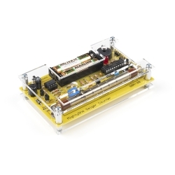
This is the SparkFun Decade Resistance Box, an involved PTH soldering kit that allows you to quickly and accurately dial in a specific resistance value between 0 and 999,990 Ω, in 10 Ω increments. The concept is simple, a decade box is a tool that contains resistors of many values that can be accessed via mechanical switches. All you need to do is just adjust the knobs to output any of the discrete resistances offered by the box. Once assembled, each kit will have controls that correspond to the digits in a decimal number - a control for the tens position, a control for the hundreds position, and so on.

The SparkFun Decade Resistance Box not only provides a challenging soldering experience but also a great tool for any workbench. In the Documents section below you will find an in depth Hookup Guide that provides you with assembly instructions, an enclosure walkthrough, and an operation guide.

Note: The rotary switches included with the Decade Resistance Box can be very difficult to turn! Make sure to check out the Recommended Products section below for knobs that will work with this kit.

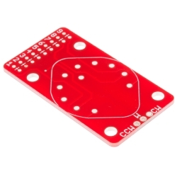
  • 1x Decade Resistance Box PCB
  • 1x Red Binding Post
  • 1x Black Binding Post
  • 5x Rotary Switch - 1-pole 10-position, with dress washer and hex nut
  • 9x 10 Ω Resistor - 1/4 W, 1%
  • 9x 100 Ω Resistor - 1/4 W, 1%
  • 9x 1000 Ω Resistor - 1/4 W, 1%
  • 9x 100K Ω Resistor - 1/4 W, 1%
  • 9x 10K Ω Resistor - 1/4 W, 1%

SparkFun Decade Resistance Box Product Help and Resources

Decade Resistance Box Hookup Guide

December 4, 2014

How to assemble the decade resistance box, then use it as a design and measurement tool.

Core Skill: Soldering

This skill defines how difficult the soldering is on a particular product. It might be a couple simple solder joints, or require special reflow tools.

2 Soldering

Skill Level: Rookie - The number of pins increases, and you will have to determine polarity of components and some of the components might be a bit trickier or close together. You might need solder wick or flux.
See all skill levels


Core Skill: DIY

Whether it's for assembling a kit, hacking an enclosure, or creating your own parts; the DIY skill is all about knowing how to use tools and the techniques associated with them.

1 DIY

Skill Level: Noob - Basic assembly is required. You may need to provide your own basic tools like a screwdriver, hammer or scissors. Power tools or custom parts are not required. Instructions will be included and easy to follow. Sewing may be required, but only with included patterns.
See all skill levels


Core Skill: Electrical Prototyping

If it requires power, you need to know how much, what all the pins do, and how to hook it up. You may need to reference datasheets, schematics, and know the ins and outs of electronics.

2 Electrical Prototyping

Skill Level: Rookie - You may be required to know a bit more about the component, such as orientation, or how to hook it up, in addition to power requirements. You will need to understand polarized components.
See all skill levels


Comments

Looking for answers to technical questions?

We welcome your comments and suggestions below. However, if you are looking for solutions to technical questions please see our Technical Assistance page.

  • Member #1673282 / about 3 years ago / 1

    I like the decade box a lot. There is nothing like it in this price range, and a bit more expensive products have simple switches instead of dials. I only wish that the banana plugs were of a better quality.

    I have designed an 3D-printable enclosure, check it out! https://www.prusaprinters.org/prints/64367-sparkfun-decade-resistance-box-printable-enclosure

  • Tenacious_Techhunter / about 9 years ago * / 7

    Seconding some of the things already said...

    Problems with the current description: Fixed!
    No tolerances listed for the resistors
    No wattage listed for the resistors

    Problems with the kit as designed:
    Using the same resistor value in series accumulates tolerance error
    "Looped" resistors introduce impedance, which is inappropriate for a piece of test gear
    Traces should be extra thick and as short as possible to minimize additional resistance; alternately, the trace length should be matched to the resistors, to bring the total resistance to a precise value
    No nice box to put it in

    Make the 2.0 version a long rectangle, sort of like a power strip, with the binding posts on the low resistance end. That way, you can read the value straight across.

    Other changes should include:
    Each resistor should be the ONLY resistor used for that value of that digit; no resistors in series for the same digit, which accumulates tolerance error!
    "Lay Flat" resistor through-hole spacing, to eliminate the "looped" resistor impedance
    SMD pads between the through-hole pads, to install more precise SMD resistors

    Options should include:
    A selection of resistor kits, so people can install the precision they require, in through-hole and SMD
    A nice box to put it in, either with numbers on the box, or numbers on the silkscreen, so the selected values can be seen
    A selection of knobs to use with the nice box

    Remember that, as the resistor values go up, the tolerances must go up as well. For instance... If you are using individually selected 1% resistors for 10 Ohms through 90 Ohms, 0.1% for 100-900 Ohms, and so on through the digits, there will still be an error accumulation of up to 4.5 Ohms across the whole box. This would be MUCH worse if all the resistors were in the same percentage of tolerance, because a 1% tolerance on 900k Ohms is 9k Ohms! This would mean that 3 digits on the box are always completely wasted for any purpose!

  • Mr Electrical / about 9 years ago / 5

    Quick Statistics and Tolerances Lesson:

    When it comes to adding resistors in series, there is no "accumulated error" percentage wise. If you put a 10K 1% resistor in series with another 10K 1% resistor, you will have an equivalent 20K resistor with a 1% error. In maths maxError = 01*10000 = 100. maxErrorOfEquivalentResistor= 100+100 = 200. equivalentMaxError = 200/20000 = .01 = 1%. <<See! 1%! No error was "accumulated" ;)

    Depending on the distribution of resistances, it is wholly possible that adding more resistors in series can INCREASE their accuracy. How? Let's say we again add two 10K 1% resistors in series. One "10K" resistor is actually 1% higher than 10K, or 10100 ohms. The second "10K" resistor is actually 1% lower than 10K, or 9900 ohms. 10100+9900 = 20000 = 20K spot on.

    While the aforementioned example was a "perfect" example, the resistances LIKELY have a gaussian distribution (bell curve) centered at the nominal resistance. The way the resistances add together, for each new resistor you add, the thinner that bell curve gets and the smaller the possible error becomes. In the physical world, that tells you that the higher numbers you select will be a whole lot more accurate percentage wise than the lower resistances will be.

    • AdamTolley / about 9 years ago / 2

      This was my thought on the issue of accumulated error.

      I have heard that the the resistors don't actually distribute over a Gaussian / Normal / Bell shaped distribution however; instead they look like a bell with a notch removed from the center - that notch being the higher precision resistors removed from the batch. This would not weaken your case however, and may actually strengthen it.

  • Member #500723 / about 9 years ago / 2

    I am curious where I can pick up just the 1-pole 10-position rotary switches?

    • Member #500723 / about 9 years ago / 3

      Nevermind. Found some here: http://www.aliexpress.com/item/10-Pcs-1P11T-1-Pole-11-Position-6mm-Knurled-Shaft-Dia-Band-Selector-Rotary-Switch/1983911649.html

      • cmonaco / about 9 years ago / 2

        Thanks! I was thinking the same thing! Sparkfun should carry these switches!

        • Member #466449 / about 9 years ago * / 1

          They're carrying them now!

          Switch: https://www.sparkfun.com/products/13253

          Breakout board: https://www.sparkfun.com/products/13098

  • Dragon88 / about 9 years ago * / 2

    I just noticed that a dead short through the box is possible if all switches are in the zero position. I could see this being an issue if someone hookups it up and turns on the power intending to set the value afterward, and has no other current limiting resistors in the circuit. User error for sure, but you still might want to make a note in the hookup guide.

    By the way, critiques aside, thanks to the designer for making this. I'm looking forward to receiving mine. I think with some tweaks it will present very good value and functionality at the price point. And the red PCB with the rotary switches is almost too cool to hide in a box. I will be modifying mine with SMD resistors, I'll "report back" if it works out well.

    • Hugo / about 9 years ago / 1

      The short options is useful to zero the system minimum resistance if you were to use this as a precision load. But this can't really offer precision measurements anyway.

  • Hugo / about 9 years ago / 2

    Unfortunately this is a very poorly designed resistor box with accumulating errors everywhere. This should only be used for rough measurements...

  • Alex the Giant (Former SFE Engineer) / about 9 years ago / 2

    It's too bad you guys didn't use a reverse mount switch. Then you could add numbers on the silkscreen and get the board to fit in a hammond box or similar standard sized box. You could even sell it as an intro to SMD kit and have a nice piece of test gear.

  • Member #500723 / about 9 years ago / 1

    How would I go about setting this up to be a decade voltage box?

    I assume I need to set it up similarly to a voltage divider circuit then?

    • Byron J. / about 9 years ago / 2

      I just bounced this off some of my colleagues, and we could use a little more detail. Your question is open-ended enough that it's hard to recommend a single solution.

      • What are the voltages involved? What sort of supply input, and what outputs needed?
      • What sort of step size are you looking for? It's going to be hard to have 100,000 discernible steps.
      • How much current do you need?
      • What's the intended application?

      If you're not drawing a lot of current, a voltage divider is one possible solution. The hangup is that if you need much current, the top leg of the divider (the series resistor) limits the current it can pass. If the top leg is variable, then the available current varies with the setting. This won't be ideal for some situations.

      A possible solution to that limitation is to use an op-amp follower as a buffer amplifier after the divider. An LM358 can source 20 mA. There are other op-amp configurations you could consider, like building a gain stage that uses the decade resistance as the feedback resistor, but they'll still be limited to 20 mA.

      For more current above that, consider using an LM317 adjustable voltage regulator. You set the voltage output using a pair of resistors -- refer to the calculator linked from that page. With a heat sink, they're good to better than an Ampere.

      • Member #500723 / about 9 years ago / 1

        Thanks!

        Im wanting to use just two of the rotary switches for selecting up to 100 different voltages. The voltages would be sent to my Arduino. The sketch on the Arduino would have a list of samples to play based on the decade selection of 1 - 100. So I dont need much current. The voltages would be a max of 5V.

        • Byron J. / about 9 years ago / 2

          OK, thanks for the explanation. That doesn't seem too tough.

          If you can use two analog inputs, simply set up a pair of dividers around the switches, using whatever resistors are handy -- 1K or 10K would be an OK starting point. Use one for the ones digit, the other for the tens digit.

          If you can hang tight for a week or two, I've got a breakout PCB for these rotary switches that will make this really easy to do.

        • l0gikG8 / about 9 years ago / 1

          For a use case like this, I'd think it would be better to keep it all digital by using a rotary encoder.

          • Byron J. / about 9 years ago / 1

            At the end of the day, they're probably pretty similar. Either solution behaves about the same in the hands of the user.

            A freely-turning rotary encoder might require a display to show the current setting, and requires two digital inputs. The rotary switch requires a single analog input, but indicates the selection with just the shaft angle.

            For an Arduino project, it might come down to which approach you're more comfortable writing the code for!

        • Byron J. / about 9 years ago / 1

          The board I was hinting at in my last comment just went live.

          It's here.

          There's also a 1-to-10 version of your concept in the hookup guide that should be easy enough to grow to two switches for 1-to-100 (well, really 0-to-99. since 100 is 3 digits long).

  • Member #134226 / about 9 years ago / 1

    I would think that putting a fuse inline would deal with the zero resistance concern. I second the interest in an SMD version of the kit.

  • @Tenacious_Techhunter ... I like your excellent ideas for improvements. However I feel like your missing the point of this soldering project board. its to help someone learn to solder, build a piece of test equipment and have fun at the same time. you are 100% correct. It isn't very accurate but it is inexpensive.

    Try this simple idea to improve the accuracy to almost dead on. install a trim pot in series with the output. Then add a small cheap basic multimeter connected thru a momentary push button. This will enable the user to fine tune the resistance that they have dialed in. The button removes the meter from the circuit. Still have the issue with inductance, however if your circuit is that picky then you shouldn't be using a decade box anyway.

  • Member #225064 / about 9 years ago / 1

    The price is too high in my humble opinion. A quick look at some catalog distributors reveals that the parts for this kit come to about $10 (in quantities of 1000) plus the board ($3 at most). Even at a selling price of $20 Sparkfun would be making a healthy margin and likely sell a lot more of these. I would also like to see Sparkfun offer just the circuit board for kits like these. Just my opinion.

  • This is a "Decade Resistance DIY Kit". This is not a "box" since there's no box, knobs, etc. But looks like it could Sparkfun the bench pretty well.

    For a beginner "decade resistance box" that really is a box, try the Elenco RS-500; it has a wider resistance range, finer resistance control, and more power handling capability.

  • PLCDoctor / about 9 years ago / 1

    Knobs, must have knobs! Even without an enclosure it's always nice to have some extra leverage to turn the shafts on those rotary switches.

  • cmonaco / about 9 years ago / 1

    What's the tolerance on the resistors in this kit? I can't tell from the pictures.

  • Dragon88 / about 9 years ago / 1

    Nice kit! How about doing a run with SMD resistors instead of PTH? Maybe the SMD kits don't sell as well, but 0805s would be SO much cleaner and nicer looking on that board.

    • That probably wouldn't be the best idea. Generally most of the applications that one would use a resistor box in would exceed the power acceptance of SMD resistors.

      • Dragon88 / about 9 years ago / 1

        Not true. And even if you do need to put some power through the thing, merely stepping up to 1206 SMD resistors would give you the same power rating as the through hole resistors currently used in the kit.

        • True, they would be the same power rating. Quite frankly though, for a hobbyist, they don't need this kind of functionality, a simple potentiometer will generally do the trick for rough estimates, which is only what this box is good for. For professional work, such as time-efficient testing of power supplies, this box is horribly underpowered, sporting tiny pth resistors.

  • Cryocrat / about 9 years ago / 1

    What's the resistor and overall wattage rating for this kit?

  • Markatlnk / about 9 years ago / 1

    Any chance for a matching box to put it in?

    • dNetGuru / about 9 years ago / 1

      Look at their tutorial here : https://learn.sparkfun.com/tutorials/decade-resistance-box-hookup-guide?_ga=1.87531101.417049075.1418398579 it does involve putting it in an aluminum box but requires some minimal metal work.

Customer Reviews

4.5 out of 5

Based on 15 ratings:

Currently viewing all customer reviews.

1 of 1 found this helpful:

Super kit

Excellent overall. Parts, PCB, switches, resistors, everything is top quality. Soldering and assembling is easy. A bit hard to use without knobs though. I guess this kit could even be a great exercise for a beginner. Value for money !

1 of 1 found this helpful:

High Quality kit!

Kit includes high quality circuit board and parts.. Fast assembly. Very accurate values.

Thanks SparkFun for offering high quality products!!

You are my 'go to website' when I need parts. I'm in Kansas, so shipping is always fast for me.

1 of 1 found this helpful:

Useful, moderately priced kit..

This was the lowest cost decade resistance box I've found, and Sparkfun, as usual, provides excellent online documentation for the kit, including a 'front-panel' legend that you can print out and mount on whatever enclosure you use. The kit itself is quite straightforward to assemble, and should prove fairly easy to complete for anyone with moderate soldering skills and knowledge of circuits. The PCB is high quality and the assembled board worked fine on the first attempt.

Sparkfun also sells a sturdy aluminum enclosure that will fit the board perfectly, but you'll have to drill out holes for all the rotary switches and and the terminal connectors. You'll also want to purchase some knobs for the rotary switches.

1 of 1 found this helpful:

Great addition to my test bench

This is a well-designed kit. Excellent assembly instructions which include some good tips for using the Box. Fun and easy to put together - the board is well-marked. Uses 1-percent resistors which is close enough for my work. I bought the optional aluminum box to mount it in. The kit comes with a hole drilling guide or you can use the PCB for the marking guide - the instructions show exactly how to do this. The Decade Resistance Box instructions also include a link to a .pdf file you can print out to make a faceplate for the box.

1 of 1 found this helpful:

Very useful

I mounted this in an aluminum box. It works great, it's a lot more compact than the Elenco resistor box I've been using, so I'm getting another.

I've built my second resistor box, now. It's incredibly useful when I need an odd resistor value for a circuit I'm prototyping. I replaced the banana plugs with some I bought from Mouser because I wanted plugs of the same color and a bit better quality.

If you build the box and the resistance, when everything is turned to zero, is higher than zero, say more than 1 Ohm, be sure to check your soldering joints.

1 of 1 found this helpful:

Well Made PCB

Parts are excellent quality. Would have liked to see a panel label included.

2 of 2 found this helpful:

Loved the quality of your work of art! One warning, don't solder to the banana jacks............One buyer complained about it being a short circuit if all dials are set to "0". I think that's the definition of "zero Ohms". Only problem is trying to open the .SVG file for a front panel. Couldn't open it, or convert it to another format. Engraving shop couldn't open it, but did lay out a beautiful job. Cost only $48.00 US! Could you furnish the panel in another format?

work great!

I made 3 but used precision metal film resistors 0.1% instead of the resistors it came with. The hookup guide is great.

Resistance (box) is useful!

This is an excellent value and a very useful piece of lab equipment. Easy to assemble, well documented, excellent quality, does exactly what it says on the tin. I like it. You will definitely want to install this in a case in order to have a faceplate for the labels! I have two construction tips: 1. Install the resistors first; then, before soldering the switches in place, BEND THE LOCATING TABS FLAT, place the switches on the board, insert the assembly into the front panel, and gently hand-tighten the nuts. Now turn it over and solder the switches. This ensures that the switches all sit flat on the board with no mechanical stress when the panel nuts are tightened. 2. As soon as possible after soldering the components, carefully wash the flux off the back of the board (I used hot water, dish soap, and a toothbrush). Don't dunk the board; instead, run water across the back under a slow faucet. Avoid getting soapy water into the switches. Finish with an alcohol rinse. Flux removal eliminates the strange resistance changes that can occur when flux on the board absorbs humidity from the air and creates leakage resistances, especially across the 10K and 100K decades.

0 of 3 found this helpful:

Kit Looks Good

But not built yet - lots of soldering

Simple kit, for doing less than simple things later.

It's a pile of resistors, a big pile of them, and that about it. It's a good replacement for the potentiometers I've been using for guessing correct values. Now I can guess right values and get an accurateish reading at the same time. I wish there was an easy option for a case, however they do post a tutorial on how to make just about anything into a working case for this "boxless" resistance box. For the price, it's a nice step-up from anything else I've seen cheap, and nowhere near as expensive if you don't need an additional decimal place.

Resistance Decade

Easy to build and works like a charm. Very useful in bread boarding circuits. Has been built into a nice case with a face plate. Highly recommend this kit.

Excellent product

Easy to assemble. Very good quality PCB. Does exactly what I needed, for a fraction of the price.

Must have for any electronics work bench.

Being able to quickly dial up just the right resistance is such a time saver when working on electronics projects. No more rummaging through different resistors looking for just the right one.

Check out my build video on youtube - here.

Thanks for sharing your build video! Great job!

Great product and usability

The kit comes with resistors that are accurate enough for the average home-gamer. The rotary switches are very good quality, and the overall quality of the board is great as expected from Sparkfun. Best of all, you get the chance to assemble it yourself.