- Home
- Product Categories
- Monochrome
- SparkFun Serial Enabled LCD Backpack

SparkFun Serial Enabled LCD Backpack
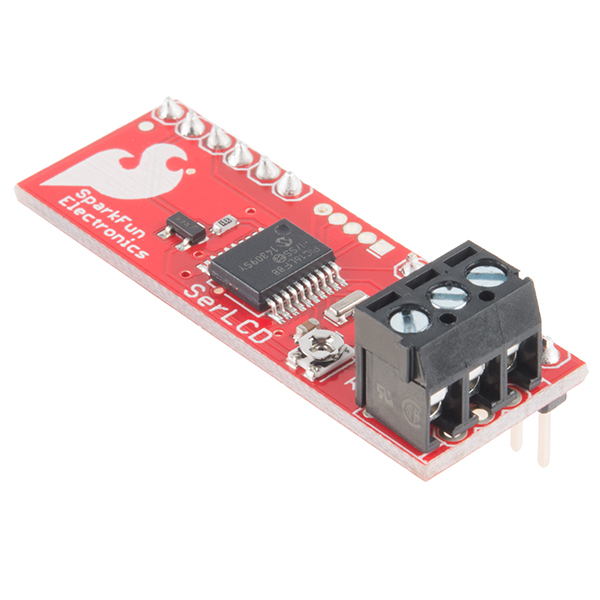
The SparkFun Serial Enabled LCD Backpack allows you to control a parallel based LCD over a single-wire serial interface. The SerLCD backpack takes care of all the HD44780 commands allowing seamless integration with any micro that can communicate over a wide range of TTL serial baud rates. The SerLCD currently supports 16 and 20 character wide screens with 2 or 4 lines of display.
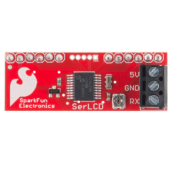
Communication with SerLCD requires 5V TTL serial at a default baud rate of 9600bps (8-N-1). You can adjust the baud to any standard rate between 2400 and 38400bps. The power, ground and RX pins are all broken out to a 3.5mm pitch screw terminal.
SerLCD has the ability to dim the backlight to conserve power if needed. There is also a potentiometer on the backpack to adjust the contrast.
Note: The SerLCD v2.5 Datasheet incorrectly identifies the PIC as a 16F688, when it's actually a 16LF88. Sorry for blowing your mind.
- PIC 16LF88 utilizes onboard UART for greater communication accuracy
- Adjustable baud rates of 2400, 4800, 9600 (default), 14400, 19200 and 38400
- Operational Backspace
- Greater processing speed at 10MHz
- Incoming buffer stores up to 80 characters
- Backlight transistor can handle up to 1A
- Pulse width modulation of backlight allows direct control of backlight brightness and current consumption
- All surface mount design allows a backpack that is half the size of the original
- Faster boot-up time
- Boot-up display can be turned on/off via firmware
- User definable splash screen
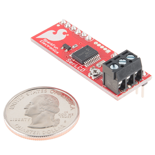
- 0.56" x 1.75"
- Schematic
- Eagle Files
- Serial LCD Application Note
- Datasheet (PIC16LF88)
- SerLCD Pin Assignment
- Quickstart Guide
- Firmware (16x2)
- Firmware (20x4)
- GitHub
SparkFun Serial Enabled LCD Backpack Product Help and Resources
PIC-Based Serial Enabled Character LCD Hookup Guide
May 29, 2018
The PIC-based serial enabled character LCD backpack is a simple and cost effective solution for interfacing to character Liquid Crystal Displays (LCDs) based on the HD44780 controller. The backpack simplifies the number of wires needed and allows your project to display all kinds of text and numbers.
PIC16LF88 vs PIC16F88
You may have noticed that there are two different PICs on the serial enabled backpacks and built-in serial enabled LCDs:
- The PIC16LF88 is populated on the SerLCD backpack
- The PIC16F88 is populated on the built-in serial enabled LCDs
You should not notice a difference when using the microcontroller for a serial enabled LCD. When selecting the device/chip ID with a programmer, you will just select **PIC16F88* as indicated from the MicroChip Forums: Need Info about programmer for PIC16LF88 series.
Core Skill: Soldering
This skill defines how difficult the soldering is on a particular product. It might be a couple simple solder joints, or require special reflow tools.
Skill Level: Noob - Some basic soldering is required, but it is limited to a just a few pins, basic through-hole soldering, and couple (if any) polarized components. A basic soldering iron is all you should need.
See all skill levels
Core Skill: DIY
Whether it's for assembling a kit, hacking an enclosure, or creating your own parts; the DIY skill is all about knowing how to use tools and the techniques associated with them.
Skill Level: Noob - Basic assembly is required. You may need to provide your own basic tools like a screwdriver, hammer or scissors. Power tools or custom parts are not required. Instructions will be included and easy to follow. Sewing may be required, but only with included patterns.
See all skill levels
Core Skill: Programming
If a board needs code or communicates somehow, you're going to need to know how to program or interface with it. The programming skill is all about communication and code.
Skill Level: Rookie - You will need a better fundamental understand of what code is, and how it works. You will be using beginner-level software and development tools like Arduino. You will be dealing directly with code, but numerous examples and libraries are available. Sensors or shields will communicate with serial or TTL.
See all skill levels
Core Skill: Electrical Prototyping
If it requires power, you need to know how much, what all the pins do, and how to hook it up. You may need to reference datasheets, schematics, and know the ins and outs of electronics.
Skill Level: Noob - You don't need to reference a datasheet, but you will need to know basic power requirements.
See all skill levels
Comments
Looking for answers to technical questions?
We welcome your comments and suggestions below. However, if you are looking for solutions to technical questions please see our Technical Assistance page.
Customer Reviews
4.3 out of 5
Based on 4 ratings:
0 of 1 found this helpful:
ok,but !!
The I2C Backpack did eventually work. I had a lot of trouble finding and installing the files to make it work. working with files in the Arduino IDE. is hard for me to understand. unzipping and putting files into folders and then having to rename them and move them around is above my ability. Spark fun products are good I have used your products in the past and will continue to buy from Spark Fun. It would be nice for people like me, if you offer software, to make it auto install and no errors!!! and also a good schematic would be nice. Keep up the good work.
Works Great!
I had this up and working very quickly. I only gave it 4 stars because: There is discrepancy on the interwebs on whether it requires 5v or 3.3. Since I used this with an electric imp I had to pull in a 5v power source. Documentation seemed lacking on the pinouts to connect this to the LCD. I'm curious if you can send special characters to the LCD through this board. I didn't see anything in the documentation on that either... All in all, provides basic control of an LCD with 1 wire.
Good product
Easy to assemble
Just what I needed
I purchased this to drive an LCD I was using for a project. It's very easy to implement and makes it simple to include the LCD of your choice in any situation. Well done.
-------------------- Tech Support Tips/Troubleshooting/Common Issues --------------------
**Default Characters and Lines for Serial Enabled Backpack **
Looking at the production test procedures for this board, the default is set to the 16 characters and 2 lines . If you are using a 20x4, you just need to send a command byte ( 0x7C ) and the associated value ( 0x06 ) to configure the serial enabled backpack for a 20x4 Character LCD.
What resonator, PNP and value of trim pot are you using? The schematic doesn't say.
A suggestion and a question: * If there is a board spin in the works wonder if an optional level shifter could be added to the RX input? Goal would be to allow a 3.3V processor (Particle Photon etc.) to drive a 5V LCD. I realize there are 3.3V LCDs available but the one I want to use is not available as 3.3V. * What is the difference in the 16x2 and 20x4 firmware? Haven't done a line by line comparison but it looks like either version could be used although 20x4 has an newer date.
Watch out! As shown in the schematic, this board has no current limiting resistor in the backlight drive circuit! Some LCD displays have built-in resistors permitting direct connection to a 5V supply, and their datasheets will say something like "Backlight 5V @ xx mA". But many (including some sold by SparkFun) do not. In that case, the datasheets may show backlight connections named LED A (anode) and LED K (cathode) and list a maximum forward current and a corresponding LED voltage drop. If you have the second type of LCD and you hook up this board, it will attempt to drive the full supply voltage across the backlight LED. SparkFun needs to add a resistor to the design and a jumper to bypass it when safe to do so.
While you're at it, you also need to add a pull-up resistor on pin 4 (Vpp). This pin is an input (not input/output) and should not be left floating. Another pull-up on the RX pin would also be advisable. Your custom-built serial-enabled LCDs are also in need of these.
The reason the LED series resistor isn't included is that the board may be used for different backlight colors, and different colors have different LED voltages. The resistor value must be adapted to that.
I'm new to this and found the datasheet unclear and inconsistent about how to clear screen etc.
Serial.print(0x7C, BYTE);
Serial.print(0x01, BYTE);
Just wasn't doing it!
Several hours of searching finally answered the question! to clear the screen you use this;
Serial.print(0xFE, BYTE);
Serial.print(0x01, BYTE);
A really useful explanation and more info is to be found here;
http://www.arduino.cc/playground/Learning/SparkFunSerLCD
No author mentioned, but thanks whoever you are! :-)
Got this to work great!
Thanks for the link HP22UK, it was a great help.
I will be getting a few more of these soon for the rest of the LCD's that I have.
Interesting behavior with an OLED display.
Newhaven Display NHD-0420DZW-AG5 paired with a serial backpack gives good operation but often swaps lines - instead of lines 1 2 3 4 (character positions 80 C0 94 D4) I get lines 2 1 4 3 with the same addresses. So line 1 is where line 2 should be etc. Resetting the driver uP does not fix this, but enough power cycling and it eventually "gets it right." My setup:
The source files provided do not match the current hardware. You can easily see this from the hardware port definitions.
For example, the source says:
define BL_Control PORTA.4
But backlight is clearly controlled by pin#1 (PORTA.2).
Can you provide the updated source code? I bought a couple and wish to change their operation.
Will this work with the 16x2 3.3V LCD? I am afraid that it will only work on 5V ones
I believe it will handle 3.3V operation, but you have to power it with 3.3V and use 3.3V serial levels.
In theory you should be able to use any voltage that the PIC can handle, I assume 2V - 5.5V should be a safe window.
Just as long as the power and serial level matches.
I am using a PICAXE 20m chip and I don't know what the serout command should be can someone please help me here.
I prefer 0.1" headers for low-voltage over screw terminal (whatever the pitch) . So, Sparkfun, be nice guyz and please fix this. :-)
I would like some more information on the splash screens. How do you change them?
Does anyone have a fritzing part made for this?
I just made a Fritzing part for you. It is now on the Github Fritzing Repo under Products/LCDs. Please comment back if you need any help! :)
Thank you. That was perfect.
Would this work with a 16x1 LCD, I'm retrofitting an old piece of equipment and that's all that will fit.
You'll need to check the pinout of the screen you are using to check for voltage compatibility, and will likely have to hack into the backpack code to get it to work properly on a 16x1 screen.
Please, is there any guide how to upload firmware into soldered PIC 16F688? And can I apply the same process for the Serial Enabled 20x4 LCD - Black on Green 5V?
Can I use one of these to read the commands from another LCD controller? I would like to for testing purposes, verses using a camera and voodoo magic to decipher what I've written.
I got this; but I'm unable to find pin identification (pins that connect to LCD) anywhere. Help!
For Arduino, I have good experience with this and the Arduino using the SerLCD from Arduino.cc library. I also added some functions for the 2.5 firmware (setType, let's one set the type of display; scrollLeft and scrollRight, scrolls the text to left or right).
http://playground.arduino.cc/Code/SerLCD
Can you use the 8x2 LCD with this?
Are they ever going to update this to allow for the RGB displays? Would be awesome if I could use a negative RGB serLCD.
I have the backpack working once again on the Arduino Uno using IDE 1.0.1 and the sketch Write_LCD from the Arduino Examples. Since the very same serial pack LCD works fine on the picaxe the problem must be with the serial output of the Arduino so I disconnected the serial wire, programmed the arduino for a blink led program just to clear the lcd program from its memory then I remove the serial wire to the lcd, uploaded Write_LCD and while the program is running then re-attached the serial wire to the Arduino, pin TX of course.
What I'm thinking is that the Arduino sends data to the TX pin that screws up the serial backpack, perhaps its the . Anyway here is the original program with my changes, messy so the changes are obvious. /* Analog input
reads an analog input on analog in 0, prints the value out.
created 24 March 2006 by Tom Igoe
This actually works with the sparkfun LCD using Serial.write Question, how do I send binary?
ADDED delay at the program start. The display was correct then something flaky happened in the LCD causing garbage to display
*/
int analogValue = 0; // variable to hold the analog value
void setup() { // open the serial port at 9600 bps: Serial.begin(9600); // Serial.flush(); }
void loop() {
delay(2000); // read the analog input on pin 0; //analogValue = analogRead(0); //Serial.print(254); Serial.write(254); //control code delay(50); //Serial.print(01, BIN); //Serial.write(01); //control code to clear the lcd screen fe+01 analogValue = 75; // the letter K // print it out in many formats: Serial.write(analogValue); //Serial.print(analogValue); // print as an ASCII-encoded decimal //Serial.println(analogValue, DEC); // print as an ASCII-encoded decimal //Serial.println(analogValue, HEX); // print as an ASCII-encoded hexadecimal //Serial.println(analogValue, OCT); // print as an ASCII-encoded octal //Serial.println(analogValue, BIN); // print as an ASCII-encoded binary
// delay 10 milliseconds before the next reading: delay(1000); Serial.write(254); // FE control code to clear the LCD, works Serial.write(01); // control code to clear the lcd screen fe+01 AOK Serial.write("now is the time"); delay(500); }
I'm using this back pack at 9600 successfully with the picaxe 20x2 but when its used with the Arduino UNO and IDE 1.0.1 I get jibberish except for one time so I added a 5 second delay as the first line of the Write_LCD program and changed all serial.print to serial.write commands but do not know what to do with BYTE data type as it is no longer valid in Arduino 1.0.1 . Unfortunately, the display is back to jibberish but still works fine with the picaxe 20x2. That doesn't make sense.
Any help with Arduino serial to this LCD would be appreciated.
Sorry I'm a novice and hope someone can help. I got this module connected to a crystalfontz hd44780 parallel 4x20 LCD, hooked up to a debian linux on ttyS1 (0x2F8). Trying to get it to work with lcdproc, but not able to display anything. I'm using hd44780 driver, and tried various ConnectionType for serial, including picanlcd, lcdserializer, los-panel. set the baud speed to 9600, device=/dev/ttyS1, lcdproc will load the driver, but the log keep showing LCDd: screenlist_switch(s=[_server_screen]) LCDd: screenlist_process()
I read another post from DoctorWho here that it is working with lcdproc. Can someone please shed some light on how I should configure lcdproc to work with the backpack? Thanks.
Just to note, I'm able to send text on linux to the LCD with no problem, e.g. echo 'Hello World' > /dev/ttyS1, so hardware and connection should be no problem, just trying to figure out how to get lcdproc to work with it.
No 115200kbps? I'm disappointed; that's my default for on-board serial comms.
The LCD itself is far too slow to keep up with that speed.
Right, but isn't there an 80 byte buffer? For me there is value in being able to get a print-to-LCD completed as quickly as possible, since in many cases I'm doing a software UART and must make the UART simulator atomic.
I received this unit today and installed it on a bread board with my 16x2 display. I then connected to an Arduino (Model: Ethernet as follows)
Arduino (GND) to BackBack (GDN) Arduino (5V) to BackBack (5V) Arduino (Tx) to BackPack (Rx)
I then powered up the arduino and saw the “Sparkfun.com SerLCD v2.5” on the LCD and then it went away. I did a quick hello world sketch for Arduino at 9600 baud and uploaded to the arduino. Unfortunately, all I got was gibberish. I saw several reports of receving the unit set to the wrong baud rate. I then wrote the following sketch to test the baud rates and reprogram the device to 9600 baud.
int g_iBaud = 2400;
void setup() { // g_iBaud = 4800; g_iBaud = 9600; // g_iBaud = 14400; // g_iBaud = 19200; // g_iBaud = 38400; Serial.begin(g_iBaud); // delay(1500);
}
void loop() { Serial.write(0x7C); // Special Char Command Serial.write(0x0D); // Reset to 9600 Baud delay(10);
Serial.write(0x7C); delay(10); Serial.write(0x04); // Set for 2 Line LCD delay(10); Serial.write(0x7C); delay(10); Serial.write(0x06); // Set for 16 column LCD delay(10); Serial.write(0xFE); //command flag delay(10); Serial.write(0x01); //clear command. delay(100); Serial.write(0x41); // Write out the letter 'A' delay(10); Serial.println(g_iBaud); Write out the Set Baud Rate. delay(1000); }
I have tried each ot he supported baud rates and still have not had any luck getting the device to give me anything but gibberish after the spash screen goes away. I have also tried adjusting the various delays.
Thank you in advanced for any help,
Is the link to the datasheet broken?
Should be up now! :)
In normal operation it works absolutely fine with my 20x4 Display, very happy with it. For in-car use I tried a little modification: I interrupted the connection LCD Pin2 (+5V) to this LCD Backpack. Then I wired up Pin 15 (LCD Backlight +5V) to Display Pin2. Planned was to turn off the whole Display together with the Backlight, to save Power. Result: Turing off the Display works fine, but when I turn it on, Line1 and 3 are full of black squares, and noting else. I turned Backlight to 100%, so there shouldn't be any PWM Problems.... Any Idea how to solve the Problem? Is there any possibility to completely switch off the display for Power saving, and just keep the backpack alive?
thanks from Switzerland, Michael
Got this backpack hooked up to my 8x2 LCD, and Netduino Plus. Looks nice.
Have anyone tried to make this backpack from scratch with these files (PCB and Firmware)
Im trying but im failing again and again. I have PIC16F88(PDIP not SMD) and 10MHZ crystal. But i cant get it working.
Can anyone help ?
Hmm, seems the manual and the circuit doesn't match. SF tell me the circuit is correct and that they are going to look into sorting the manual, so go with the circuit I guess! :)
Has anyone been able to control the back light brightness? I have communication with the LCD, but none of the commands seem to adjust the back light brightness. Other than that, this product works well with my 20x4 LCD
I have ported LiquidCrystal library for use with the serial LCD you can look at my code here. Still working on finishing all the documentation. But putting up for now hopefully someone will find it usefull.
http://arduino.cc/playground/Code/SerLCD
-Thanks
I haven't been able to successfully change the baud rate and I haven't been able to find anyone on the internet that have either. Can someone from Sparkfun please respond to this message telling us how to change the baud rate? Thanks
Tip: ensure that you are not sending any data to the backpack for the first second after powerup. If this happens, the backpack will revert to 9600 baud as a safety measure in case you don't know what baud rate you set it to. Note that connecting this to an Arduino's serial port WILL send data to it when the system is powered on, as the bootloader will try to connect to a host computer if present. If you connect the backpack to another set of pins using NewSoftSerial, this won't be an issue.
Thanks for the tip about reverting back to 9600. I'll try it again, but I am pretty that's not the issue because I'm already using the NewSoftSerial library.
From experience, it does work. Ensure you're sending the correct binary bytes listed in the datasheet, not ASCII characters. I've done it by hand using the terminal program realterm, which lets you send individual binary characters. You'll also need to power-cycle the backpack/display to get the new baud rate to take effect.
I'm on a mac, is this right? 0x7C and 0x10
That looks right for 38400. If you're using an Arduino, the statement is Serial.print(0x7C,BYTE); If you're in straight C, putch(0x7C); or printf("c",0x7C); should work. Wait at least 1 second before sending the sequence. You might put in a short pause (10ms) between the characters and after to give it a chance to store the value in EEPROM. Then power cycle the display, wait 1 second, and see if it works at 38400. One last thing to try is to put a 1K resistor to 5V on the serial line; the backpack may be receiving noise while the newsoftserial line is in a high-impedance state; this will ensure the line stays idle before newsoftserial starts up.
Everything you suggested I either already knew or had tried before with the exception of the 1k resistor, which also didn't work/help. I am really starting to think it's not possible, I've seen tons of post where people weren't able to change the baud rate and no one ever posted a solution or that they were able to it.
Put this on a 20x4 parallel LCD. The included firmware seems to be for a 16x2 cause I cant access the bottom 2 lines of the 4 line display.
I assume I need to load the 20x4 firmware. Can this be done with an arduino or netduino?
I ordered LCD-09067 which is white on black serial LCD. It worked with orignal package.
using MPLAB with PICKit 3, I could load the modified version which was from serLCD-v2.7, however, it did not work for some reasons. After that, I reloaded the orginal firmware from SerLCD-v2.zip or SerLCD-v2.7xx.zip. Neither did it work. I doubt the firmware and source code are not the working version.
Any ideas?
Mine displays garbage characters when the input is floating. I am using it with an Arduino (using softserial so it doesn't conflict with the USB->serial) that configures all pins as high impedance inputs on reset, which immediately overwrites whatever is on the display. Perhaps the next rev could include a pull-up resistor on board?
To create and use custom characters go here.
Bought this to go on my 16x2 LCD. The LCD backlight turns on, but I get no splash screen, and it is unresponsive to all commands. Occasionaly the backlight will shut off or blink on and off slowly. I took it and hooked my LCD up parallel again, and it works perfect. Any ideas? Maybe I'm just not grasping the concept of TTL, but any and all code examples I could find produced the same result.
Tip #1: Want faster refreshing when using the LCD-0255? Use cursor addressing as described in the SerLCD V2.5 Datasheet.
Tip #2: To prevent loss of serial comm between the MPU & SerLCD, include in the INIT portion of your program to set the speed (9600) and clear the LCD display else at times the SerLCD and LCD display will fail to display past the power on 'Splash Screen'.
Tip #3: program the splash screen with the program name and version being run or tested. Update when the program version changes. These steps help as a reminder as to what your were last working on .
I'm trying to set the Splash Screen on this version 2.5 LCD Back Pack with LCD.
The Back Pack docs says to setup the LCD message and then send 124 and J. What is the decimal or hex representation of Control J?? Here is my code, control J ?????
main: hserout 0,(0xfe,0x01) ;clear lcd
pause 100
hserout 0,("SPLASH N CUR")
hserout 0,(254,199,"X",124,"j") ;set cursor pos and make the splash screen.
??? thanks ,,,, Bill
I'm trying to get the serial LCD backpack to work with an MSP430 launchpad and Powertip pc2004m 4x20 lcd.
My first problem is no splash screen on power up. LCD is lit but blank. Any suggestions are appreciated.
Before applying power, I was studying the backpack to make sure I understood which pin was which and ended up having to unsolder the screw terminal connector block to repair an open trace under the connector. There was no continuity from the 5V screw to the nearby 5V header pin, JP1 pin 5.
As a matter of fact, initially there was no continuity from the 5V screw to anywhere at all.
So, there were two problems, an open trace, for sure, to the header pin, and a bad solder connection from the screw terminal pin to its hole, so that the 5V trace that leads to the components was also not connected to the 5V screw. After fixing the open trace and resoldering the connector, the board powered up OK and works fine.
I use HyperTerminal to send the commands and control characters. Use the ALT key and numeric keypad or equivalent keyboard numeric keys.
On a black on green 20x4 lcd, the backlight flickers quite a bit. Any suggestions on how to eliminate it? It's being powered from an Arduino UNO's 5V line via a breadboard.
That could be a bad connection if it flickers if nothing is going on or when you wiggle wires. If it flickers when changing text it's probably your arduino not supplying enough current.
I am trying to change the baud rate on my SERLCD_v2 but am getting no joy. The datasheet says to send (124, control m) but I have tried all possible combinations and it keeps receiving at 19200. Could anyone please tell me what the code should exactly look like.
I am using a picaxe 20X2.
Thanks
Could someone please explain where pin 1 is? I'm asuming it is the pin above the dot & "spark" logo that are both on the side with the PIC...
--Thanks--
That is actually pin 16. Pin 1 is on the opposite side.
is there a way to hook this directly up to a usb cable to program it?
If so how does one do so?
Thanks
You would use an FTDI basic. For actual firmware programming, you would need a PIC programmer.
Ok i'm having trouble changing the baud rate and saving the splashscreen.<br />
The manual says "j" to save the splash screen, however theres no way i can get that to work.<br />
What is "j"?<br />
i tried sending J i tried sending j tried even sending "controlj" and "j" and another half dozen variations.<br />
How the heck do i perform a "j"<br />
Hello,
What is the part number of transistor on this board?
Thank you.
Thank you, Robert.
" by RobertC. is a SparkFun employee
RobertC.
| Sep 28, 2010 at 1:02pm
Yep. I'm working on revising this whole page with new and updated information. In the meantime, you can email techsupport@sparkfun.com and get what you need."
I found this on your forum back in March.
I am hoping to roll my own.
Any help would be appreciated.
Thank you
"Bonz099
Post subject: SerLCD 2.5 Hex?
Posted: Sun Mar 07, 2010 3:33 pm
Replies: 0
Views: 54
Im having trouble locating the hex file for the v2.5 serial backpack all I see on the site is the 2.0 version. When I write it to my backpack via the ICSP header it just gives me 2 black lines (row 0 and 3). Also if someone had the source+updated schematic for it as well, that would be VERY helpful,..."
Yep. I'm working on revising this whole page with new and updated information. In the meantime, you can email techsupport@sparkfun.com and get what you need.
Circuit showing 16F88, but manual showing 16F688. Not sure what the Eagle files showing.
Any chance of updating this?
Thanks
Schematic and eagle files are correct. I'm also getting a new picture shot now. I'll make a note about the manual.
"SFE, could you please post the schematic and source code for v2.5? The versions you have now appear to be the v2 (with the 16f688). Thanks!"
Also,
Picture of backpack shows a 20 pin device and crystal.
The 16f688 is a 14 pin and should not have a crystal according to the manual.
Manual picture appears to be right.
Thanks
I've bought one of these.
I don't seem to be able to make it work!
no matter what I do I can't print anything on the LCD! And I keep getting the splash screen!
The specifications says the splash screen comes on after 500ms, it doesn't! It comes after probably 10 seconds! Then when it's on the backlight keeps flashing on and off!
Any help?
Please contact techsupport@sparkfun.com. Thanks!
Nice gadget!
Just got 15 pieces to Finland, and made them to work with a PICAXE processor. If someone is interested what settings should be used, it is here: http://www.picaxeforum.co.uk/showthread.php?p=134442#post134442
As I said ,a very nice product, but the manual really needs a little shaping...
Most things are already discussed here, and could be "transferred" to the manual.
AND a little warning! I noticed that in many lcd's ,pins 15 and 16 can be next to pin1 !
So, check carefully Your lcd's datasheet, else You could stick the backpack to all wrong holes...
Great product. Saved me lots of headaches with a 20x4 LCD, HD44780-compatible.
I tested it on my PC using the 5V FTDI serial breakout "DEV-09115" also bought here.
The command for enabling/disabling splash screen (0x7c-0x09) is not yet documented in the PDF datasheet. The setting is saved in the EEPROM for next reboots.
I had to reboot (power cycle) the LCD display after every command changing the LCD setup (0x7c-0x03 to 0x7c-0x06); anyway, these are stored in the backpack EEPROM as well, thus once set I don't need to use them anymore.
My software just issues a 0xfe-0x01 sequence (clear display) and 80 characters (blank-filled). The 9600 default speed is more than enough for that (less than 0.09 seconds for sending a full screen update).
I was also able to define graphical characters sending the command 0xfe-0x40 and then from 1 to 8 sequences of 8 bytes containing the bitmaps (for example 0x15-0x0a-0x15-0x0a-0x15-0x0a-0x15-0x0a will define a 5x8 checkered pattern) and finally a 0xfe-0x01 (clear screen ending bitmap definition mode). The defined characters are 0x00 up to 0x07. Characters are stored in CG-RAM of the display; this means that they will have to be redefined on every reboot.
Hi,
I am trying to connect a 20x 4 LCD to the pic but can't understand how to connect the pins. Can you please give me a link to the sheet you were following to connect the pins of the pic to those of the LCD please?
Thanks.
Could somebody please clarify the waveform needed to communicate with this device?
1 Start Bit, 8 Data Bits and 1 Stop Bit. Doesn't tell me enough.
Is this active-high or active low? What should be the polarity of the Start and Stop bit, and what should the RX pin be forced to in the idle state, or when we are not transmitting data??
I'm trying to get this to work via an FPGA and I'm having weird results.
Thanks!
I dug into the Atmega datasheet and found the details of the USART. Looks like idle is always logic high. Data is active-high. Start is always low. Stop is always high. Data is sent LSB to MSB
Using this I got it working for the FPGA, so I assume it is correct.
Anyone got advice on controlling multiple HD44780 LCDs with a single backpack? New to micros, can I just independently wire up the enable and add all the LCDS to a single "bus"?
Long story short... this is not (feasibly) possible. You would need a complicated (okay probably not impossible) way to "bank" the data from the backpack to the multiple lcds, which may even require more logic intervention. There is no way to address the hd4470 chip individually in a parallel connection, each controller needs it's own bus. And each backpack needs it own bus (1 wire (+gnd @ Vcc), if it were i2c you could control multiple backpacks from one bus. I would only do it to prove a point (which is sometimes all the reason you need!!!) SO, you need one backpack AND one pin on your uC for each LCD. Hope this was of help!
EDIT
Just re-read your post. You might be onto something! The enable pin might work as a "banker" just as long as the display retains the display, and ignores incoming data while the enable pin is low (or "not enabled") . This of course would require an extra pin per-display, coordinated with the data going to each display. Just try it, and let everyone know how it goes! If I had a project using multiple displays, the insight in your question would be invaluable. I would have just used a separate controller and bus for each display, or I would have found an i2c solution. A little tweak here and there can save a lot in production!!!
It wouldn't necessarily need an extra pin per-display. You could use a decoder to drive the enable lines.
Backlight off doesn't seem to work (at least with the source code zip provided).
backlight_counter is being incremented and then checked if its equal to brightness_setting, which will never occur if brightness is 0. So off is the same as 100%.
Although I suspect the intention was to disable the timer interrupt if brightness_setting = 0?
I agree with the need for a little clarification in the docs... my (also recycled) Sharp LCD has a 2x7 (data) + 1x3 (backlight LED) header for the interface, so does not plug straight in... where is pin 1 on the backpack? There is a suspicious dot at the far end away from the serial/power screw terminals, but it IS NOT PIN 1!!!! There is a cryptic reference in the datasheet to pin 15/16 as being near the sparkfun URL, [which is not on the current board...] (but is in the image in the datasheet). Once I got that sorted, it works great! I would suggest a diagram included with the pinout doc that shows the pin orientations.
Also on commands, it is still not clear to me what to send to program the LCD size, after the command byte (0x7C) do you send "3" [0x33] or 0x03? And how do you use the cursor (blink/underline) on/off? [which should also include the 0x09 command for blinking text?] I have the positioning commands working.
When looking at the backpack with the pins facing away from you, which is pin number 1? there are no markings on my backpack?
Also, How can i get it to communicate with a BS2?
When i recived this i had some problems making it work.
Text sent to display showed up as garbage.
Startup message displayed nicely.
After issuing a 0x12 (ctrl-R) while startup message showed, resetting the chip to 9600 baud it worked perfect.
Very nice product.
In the data sheet the "CHAR" labels could be more clearly explained. I eventually figure out that they are a type of ASCII command and found a table that list the hex equivalents for each "CHAR" command you have listed. A suggestion for future revision of this document would be to include the hex version of each command statement instead of only listing the keyboard command, since they are not always available when controlling the lcd from a microcontroller
Just a suggestion for the next revision of this excellent product. How about adding in a keypad encoder function? The encoder would scan up to a 4x4 keypad and output the key press information on the TX line of the serial port. (Similar to this, http://www.robot-electronics.co.uk/htm/Lcd03tech.htm)
Hello!
My Serial Backpack arrived when the firm more or less insisted it would.
I have just completed a trial using it with the LCD display program for Linux LCDd and lcdproc, and after configuring the program to think it was talking to a certain vendor it just worked perfectly.
Additional details, the display is one that was a "pull" I believe it was recovered from the display for an older laser printer. And the programs were retrieved from www.linuxpackages.net and the serial device talking to both is a USB breakout board for the FT232R device.
In a word, "Finestkind!".