- Home
- Product Categories
- Flex / Force
- Flex Sensor 4.5"

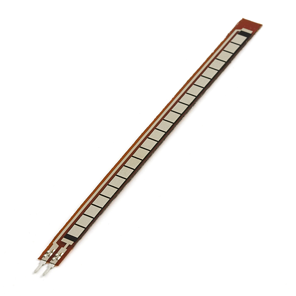
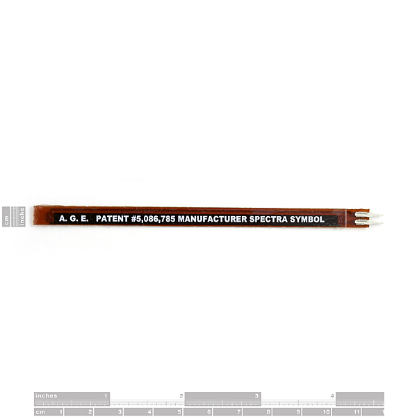
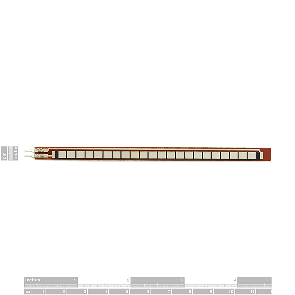
A simple flex sensor 4.5" in length. As the sensor is flexed, the resistance across the sensor increases. Patented technology by Spectra Symbol - they claim these sensors were used in the original Nintendo Power Glove. I love the Nintendo Power Glove. It's so bad!
The resistance of the flex sensor changes when the metal pads are on the outside of the bend (text on inside of bend).
Connector is 0.1" spaced and bread board friendly. Check datasheet for full specifications.
- Datasheet (FS7548)
- ITP Sensor Workshop
- Hookup Guide
Flex Sensor 4.5" Product Help and Resources
Flex Sensor Hookup Guide
May 5, 2016
An overview of the flex sensor - a bendable variable resistor. Plus, example circuits and Arduino code to get you started!
Qwiic Flex Glove Controller Hookup Guide
July 19, 2018
Is your finger bent? Is your finger straight? The Qwiic Flex Glove controller board will answer this age old question for you with the flex sensor!
Core Skill: Electrical Prototyping
If it requires power, you need to know how much, what all the pins do, and how to hook it up. You may need to reference datasheets, schematics, and know the ins and outs of electronics.
Skill Level: Noob - You don't need to reference a datasheet, but you will need to know basic power requirements.
See all skill levels
Comments
Looking for answers to technical questions?
We welcome your comments and suggestions below. However, if you are looking for solutions to technical questions please see our Technical Assistance page.
Customer Reviews
4.3 out of 5
Based on 10 ratings:
Pretty great
Although their readings to fluctuate and are sometimes inconsistent, they work how they are implemented. They are pretty flimsy and you can accidentally break the pins when you try to insert them on a breadboard. Other than that, with proper care and caution, they will provide you with the right readings for your projects. :)
Awesome sensor, needs better connections
This sensor is amazing, definitely helped with my door security project, though the connection it has with the M/F Arduino jumper cables is quite poor. I eventually just took two alligator clips and attached them to male jumpers then to the flex sensor, which is not ideal. Other than that it's great!
High Hopes For The 4.5" Flex Sensor
I am currently buried alive in another project at the moment, but I am SURE this will do the job just fine. It is "hush-hush" though...N.D.A. you understand. This is going to be fun!
The Sensor arrived fast and in great shape. I couldnt help myself and hooked it up to bet some base lines. Perfect for the application I ordered it for.
Thank you for supplying it such a great price. I think I will buy MORE! I know I will.....I'm off to my shopping cart!
Love these little things
I've been using them for years, really interesting sensors for different applications. Watch your iron's temperature if you solder them (advised). The thin contacts part flexes very well but adding some soft wires will allow you to keep that part safe.
Thats size, what cant find anywhere!
It is right price for this size flex sensor!!!
Essential part for my school project!
They work perfectly and they're quite resistant Thanks so much, Sparkfun!
Small changes recommended - laminate sensor for structural integrity and provide jumper plugs
Moderate flexing results in break between pins and sensor. Tried laminating the sensor to provide structural integrity, protect pins. Seems to work OK. Also, instead of pins why not provide solderless jumper plugs?
Works excellent for robotic hand project
These work great to control servos for our robotic prosthetic project in my biotech engineering class. I added the SparkFun blue quick connection clip to each sensor and shrink-wrapped wires to the clip to create an easier connection for students. Students then sewed the sensors onto three fingers of some cheap cloth white gloves and put a second glove over the first to keep them in place. These sensors are very responsive and act exactly as I would have hoped.
The claim is correct (I eviscerated a power glove to put it on a "better" glove (which was better than the original material, but the Power Glove's limitations made for problems still)- it is pretty much the sensor that you'll find on the three fingers they sensored on the Glove. Fragile as all get out on the connector edge. The fluctuations are an aspect of the sensor in question. Suggest you apply some filtering on the output of this device on what you're using (they did...)- direct measured data off of this is going to make you pull what's left of your hair right out if you don't. It makes for an "okay" answer for things like this. P5 armored the sensors in flexible plastic to "improve" use, so keep that in mind.
Take care how you mount these in your project.
I was really surprised when I had two of these fail after only about 700 flexings. Looking at the failed sensors I noticed what I would call a design flaw. Most of the sensor has a thick plastic backing which helps keep it from bending too far/sharply to cause damage. However the reinforcing strip ends abruptly about 2mm before the connectors and the remaining material will easily bend far enough to destroy the sensor. (If you look closely at the back product shot you can see where the strip ends.)
After applying strain relief to the connection area (gluing a couple of thick pieces of plastic across it) the life of the sensor has been dramatically improved.
The schematic in the datasheet is wrong. it should say "Vout = Vin * (R2 / (R1 + R2))". not "(R1 / (R1 + R2))".
Hi..I just want to ask..I have a flex sensor..and configured it..it works properly. But when i unhooked the sensor from the board and run the code..I was surprise because i still have reading in my serial monitor even without the sensor. I thought that i would have zero reading. Can someone explain why i still have reading in the serial monitor??..thanks :)
Hello. When you have an input not connected to anything, the state of the input is known as "floating". This generally leads to arbitrary numbers being read. This state is generally undesirable. (The purpose of pull-up and pull-down resistors is to avoid a floating input pin.)
The ITP Sensor Workship link in the product description is non-functional.
Would these still work if I put heat-shrink tubing around them?
I can't imagine it wouldn't. You'd need to be careful though that applying the heat to the heat shrink doesn't damage the sensors, and that you don't shrink the wrap to the point that it is permanently flexing the sensor.
What Toni said. I'd worry about the heat shrink "cylinderizing" the strip, which would prevent it from bending.
This sensor is great! The reviews regarding inconsistent resistance values are fair and truthful from my experience. The ones regarding connection points failing due to being flexed may be truthful, but are not fair. If you want a sensor that is 100% ready for an industrial environment, then you will pay $150-$500 for it. It will come with pretty mounting brackets, an IP66 rating, and a housing that protects the sensitive portions. This sensor is less than $15! Buy two of them and use the first one as a learning experience on how to predict points of failure due to physical and environmental stress. Some of the negative reviews regarding the connections breaking due to flex are quite unfair...they have the same worth as saying, "My non-waterproofed temperature sensor failed when I submerged it in boiling water....what a piece of crap!" Would you also mount a toggle-switch solely by two 22 gauge wires and expect it to last for 50 years in a marine environment under daily use? Of course not! The datasheet clearly defines the ACTIVE LENGTH...and it does not include the connection points...RTFM!
Can anyone please give me what is the output produced for given amount of deflection? ASAP need for a project.
You can check our tutorial for rough values of the smaller sensor, but due to manufacturing variability each sensor will be a little different. The best practice for any project is to buy one and measure the resistance yourself at your required positions.
I too was having problems with the delicate end of this sensor. After applying strain relief and renforcing the pin end, I now have severe drift! It's at ~1%/sec...really bad. Any suggestions on addressing the drift would be much appreciated!
i installed three of these and their resistance (laying flat) changed from 10k to 40k in just a few weeks. I'm not sure if it was due to temperature issues or i damaged the small unprotected part...
I'm installing new ones, but I'm using the plastic part of the old ones to reinforce them :) just an idea i had and wanted to share :)
Can you gimmi the quantitative relation between amount of resistance vs deflection. Any formulae relating to it...Thanks in advance.
this items is absolutely unreliable, it's I just waste 8 sensor after sometime using it. It's just worth about 100 flex?
I bought one of these and I am struggling to get a decent range of values from straight to fully bent. The range difference from max value to min value is about 50 on a scale of 0 to 1023. I have tried anything from a 10k Ohm pull-down to a 390k Ohm pull-down resistor and the resistor values only change where the min and max values are within the range of 0 to 1023 while the difference between the min and max values never deviates much from 50. Is there a way to get these sensors to output a range from 0 to 1023 or is this just the nature of the device?
This is quite a nice toy. Some 10kOhm when not flexed, going up to some 18k when bent at 90 degrees, and some 24-25k when at 180 degrees.
Flexing in the opposite direction shows less effect (down to some 9.4k). Apparently it can show far more than 50 different resistance values.
I want to like these... but they definitely are not designed that well. My biggest problem is that I need to re-calibrate them after a couple weeks of use. The resistance seems to change and it effects the way my projects work. I will try to strengthen the weak joint and maybe that will help.
when are these back in stock??
The datasheet link is broken. :(
These things are terrible. Absolutely terrible. I bought two a week ago to add to an e-textile project, and before I could finish, both the sensors decide that they only like to work when the "unprotected" end where the pins are is at a certain position. For sensors that are meant to be used with a lot of motion, these things are poorly designed. VERY POORLY DESIGNED.
See the comments here: http://www.sparkfun.com/products/10264
It's all about strain relief.
I hate to say it but perhaps components that move or that are physically manipulated by the end user should have a disclaimer about needing proper strain relief.
Sorry to hear that. Email techsupport@sparkfun.com if you need help with them. They should be more stable than that, although the pins can be finicky.
I reinforce mine with short, thick wires and hot glue.
Any idea where to get the connectors for these?
Thanks.
-- Rob
The pins are 0.1" spaced so it'll plug into a breadboard, or any of the female connectors or jumper wires. I'll get them into the related items list.
Bravo on the "Wizard" reference. Lucas would be pleased... :)
Here's some shots of an interesting use of these things for contact detection on a robot over at Hacked Gadgets:
http://hackedgadgets.com/2008/04/13/map-bot-floor-mapping-robot/