ATmega328 with Arduino Optiboot (Uno)

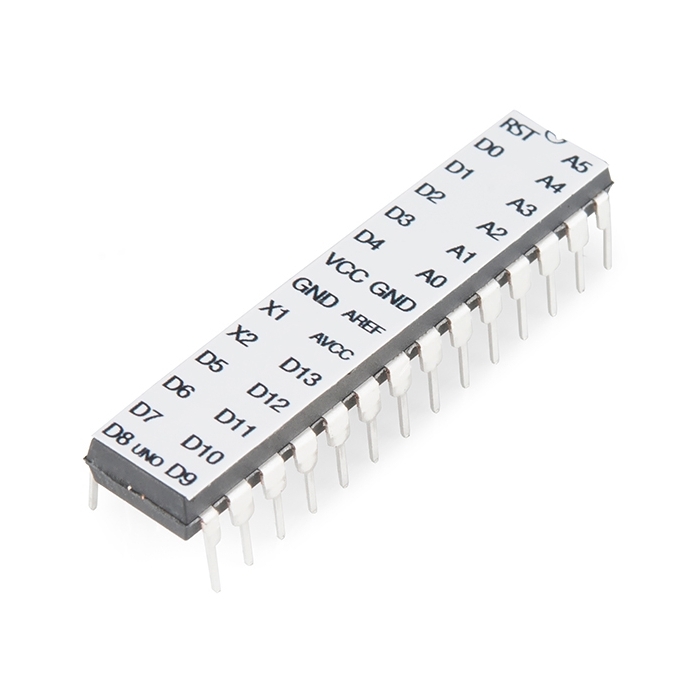
The name says it all on this one. An ATmega328P in DIP package, pre-loaded with the Arduino Optiboot (Uno 16MHz) Bootloader. This will allow you to use Arduino code in your custom embedded project without having to use an actual Arduino board.

To get this chip working with Arduino IDE, you will need an external 16MHz crystal or resonator, a 5V supply, and a serial connection. If you are not comfortable doing this, we recommend purchasing the Arduino Uno board that has all of these built into the board.

Atmel's ATMega328P 8-Bit Processor in 28 pin DIP package. It's like the ATmega168, with double the flash space. 32K of program space. 23 I/O lines, 6 of which are channels for the 10-bit ADC. Runs up to 20MHz with external crystal. Package can be programmed in circuit. 1.8V to 5V operating voltage!

Note: This microcontroller is in fact the ATmega328P, not the original ATmega328 and contains the bootloader used on the Arduino Uno, with small modifications to work more reliably with different serial connection options (mainly the FTDI). Check the link below for more information.

ATmega328 with Arduino Optiboot (Uno) Product Help and Resources

Reducing Arduino Power Consumption

November 10, 2016

A tutorial about different ways to reduce the current draw for your next Arduino project the easy way.

Choosing an Arduino for Your Project

December 11, 2017

Examining the diverse world of Arduino boards and understanding the differences between them before choosing one for a project.

Resources and Going Further

This chip is great for making breadboard Arduinos. For more information on the parts to make a breadboard Arduino and guide, check out the documentation from our old Breadboard Arduino Compatible Parts Kit:

You can also check out the tutorial from Arduino.cc:


Core Skill: Soldering

This skill defines how difficult the soldering is on a particular product. It might be a couple simple solder joints, or require special reflow tools.

2 Soldering

Skill Level: Rookie - The number of pins increases, and you will have to determine polarity of components and some of the components might be a bit trickier or close together. You might need solder wick or flux.
See all skill levels


Core Skill: Programming

If a board needs code or communicates somehow, you're going to need to know how to program or interface with it. The programming skill is all about communication and code.

2 Programming

Skill Level: Rookie - You will need a better fundamental understand of what code is, and how it works. You will be using beginner-level software and development tools like Arduino. You will be dealing directly with code, but numerous examples and libraries are available. Sensors or shields will communicate with serial or TTL.
See all skill levels


Core Skill: Electrical Prototyping

If it requires power, you need to know how much, what all the pins do, and how to hook it up. You may need to reference datasheets, schematics, and know the ins and outs of electronics.

3 Electrical Prototyping

Skill Level: Competent - You will be required to reference a datasheet or schematic to know how to use a component. Your knowledge of a datasheet will only require basic features like power requirements, pinouts, or communications type. Also, you may need a power supply that?s greater than 12V or more than 1A worth of current.
See all skill levels


Comments

Looking for answers to technical questions?

We welcome your comments and suggestions below. However, if you are looking for solutions to technical questions please see our Technical Assistance page.

  • hey just a question is this ATMEGA328P? with the P?? because i need the ones with the P on the end

    • Yes! We stock only ATmega328Ps at SparkFun. While there are some significant differences between the true ATmega328 and ATmega328P, the community has generally left off the P when talking about the chip on Arduinos. This is the ATmega328P.

  • Virgil_Disgr4ce / about 13 years ago / 16

    Hey everyone! I made a handy and easy "Breadboard Arduino" tutorial that you can plug this ATmega into. :)
    Breadboard Arduino: Fast, Cheap and Fun

  • __Tango / about 13 years ago / 3

    Can this be dropped into an arduino UNO? I think there's a problem with the flash on my current MCU on my UNO, and would like to just replace the atmega328 instead of getting a whole new arduino.

    • Pegasus / about 13 years ago / 1

      +1 on this as I managed to accidentally fry one of the A/D inputs on my UNO. Is this a drop-in, no-muss, no-fuss replacement?

      • tylerroberts / about 13 years ago / 2

        I dropped a new one of these in my Uno. Took me two days to figure out that the chip goes in upside down though. Reset pin (next to the little triangle), does not go next to the "RESET" label. I figured this out my using my multimeter on the empty DIP socket to find the VCC and Ground. So... little triangle goes on far side of the USB cable and you're golden.

        • rwizard / about 12 years ago / 2

          Ummm, upside down? On circuit boards, Pin 1 (or the pin 1 end) of a DIP socket is normally designated in one or more of the following ways: a notch in the end of the socket, dot or other mark next to pin 1 on the board, and/or square pad in contrast with round or oval pads for other pins. On the chip, pin 1 is usually marked with a small dot, and/or a notch at the pin 1 end. Glad your chip survived ;) .

          FWIW, I just dropped one of these in my Duemilanove to upgrade from the 168 that was in it. Works like a champ with no modifications or problems - just remember that your board is now an UNO as far as the IDE is concerned!

          • Member #537149 / about 10 years ago / 1

            I got a laugh from the "upside down" comment too. At least you informed him. Guess the "U" notch on the socket and the identical one on the sticker wasn't obvious enough.

            • Rippey574 / about 10 years ago / 1

              Yes, but I am starting to see a trend where people don't understand on a component level. They use shields and break out boards and just learn C variants and go.

  • Kyle Barker / about 10 years ago / 2

    Just to clarify.. this is an ATMEGA328P... not an ATMEGA328... there is a difference...

    • eqrunner / about 10 years ago / 1

      I wish I would of known this. As I have spent the last week trying to get this chip to work on a 5v system. And couldn't figure out why it was not working. Their description is wrong saying it can operate on 5v's. Sparkfun, Please correct this so others won't get this messed up

      • M-Short / about 10 years ago / 1

        This is the ATMega328P, which is the same chip used on the Arduino boards most of which run at 5V. If you are having problems getting it to work email techsupport@sparkfun.com, but it definitely does work at 5V.

      • The ATMEGA328P runs at 5V, but it also can go lower than the 328. Product Page

  • mikey / about 9 years ago / 1

    Can pins 0 and 1 be used for both dightal and serial? Just not at the same time?

    • Yessir, you are correct. If you use "Serial.begin", pins 0 and 1 are immediately reserved for serial communication. Which is annoying if you want to use the serial monitor for debugging.

  • mikey / about 9 years ago / 1

    What pins are available for INT on this part? Just 2 and 3?

  • Member #625649 / about 9 years ago / 1

    Any tutorials on making an arduino clone on Eagle? I am trying to make a customized one for a sumobot because I don't need any headers or alot of other things that take space. Currently I am using a shield to compensate but the space it takes up is a bit too taxing. Thanks

    • Kamiquasi / about 9 years ago / 1

      I suspect that the quickest route would be to download the reference design of the Arduino UNO as there are Eagle files for that available, and then remove things from the schematic and keep an eye on the board to see what changes (e.g. the headers that you don't need, but also make sure you remove the Arduino brand name, etc. where applicable). The design they offer there is for the PTH version.
      One note: when you load the file you may get a consistency error - the easiest way to resolve that is to open the .brd file in a text editor (notepad will do), look for the text "1x10@1" and replace it with "1x10". There should be two occurrences, replace both. The files should then load without a consistency error.

  • Member #625649 / about 9 years ago / 1

    How can I find this in Eagle? Thanks!

  • Member #430576 / about 9 years ago / 1

    I see that this optiboot bootloader seems to be for the Uno. Will this also work for a circuit like in Virgil_Disgr4ce's comment below? His circuit is close to a Lilypad or Pro-Mini. I also noted in the Optiboot "Change Info", above, that there was some concern about programming baud rate. Has this been addessed? I built a similar circuit using the 16MHz resonator instead of the crystal and will use your 5V FTDI Basic Breakout for programming. Will this ATmega328P with Optiboot work in my project, or, what do I have to do to make it work? Thanks.

  • LED addict / about 10 years ago / 1

    Is there a way I could program this with an UNO SMD or a redboard? Also, is there a way to program either version of the pro mini using those boards? I intend to get a FTDI breakout board at some point, but I was wondering if I'd need one to work with these.

  • Weboide / about 10 years ago / 1

    I was very happy to see that this had a sticker on it, which is the length of the chip and has all the pin names (e.g. GND, VCC, D8, D9...). Thanks Sparkfun! Very helpful!

  • is there anyway to program it with UNO? 8Mhz, no crystal, i've looked all the common but still don't understand, sorry for my silly question.

    • ender323 / about 10 years ago / 1

      You would need to burn a new bootloader-I would just pop the chip into a breadboard and wire an arduino in as an ISP. May be possible to just do this onboard the arduino. Something like this- http://oddwires.blogspot.com/2012/06/burning-bootloader-into-bare-atmega328.html

  • Member #454280 / about 11 years ago / 1

    P.O. R30364

  • Member #454581 / about 11 years ago / 1

    Cannot see Serial Port when using FTDI?

    I have assembled the "Arduino on a Breadboard" from the Arduino site and connected the FTDI as illustrated. I am using an iMac running OSX. I cannot get my Arduino IDE to display the proper serial port when connecting to the FTDI. When I use my UNO I always use serial port /dev/cu.usbmodelfd131. When I use the FTDI board I do not see this port available. Only the /dev/cu.Bluetooth-Modem and /dev/cu.Bluetooth-PDA-Sync ports show up. Note that these also show up when using my UNO but they do not work with the UNO either. If I do attempt to load a new program from the IDE I just get an error telling me that the /dev/cu.Bluetooth-Modem port is already in use (likely by my wireless mouse and keyboard). Any ideas?

    • It sounds like there may be a problem with the drivers on your FTDI board. You should be seeing a similar port as your Uno shows when you plug in the FTDI board. Double check that all of the connections on the FTDI board look good and that there aren't any floating pins or solder jumpers (excluding the voltage selection jumper on the back of course :) ). If you do find a problem, please contact our technical support team, and they'll be able to assist you further.

  • GaretBiglow / about 11 years ago / 1

    Is it possible to:

    1. Remove ATmega328 from an existing UNO board
    2. Stick in a NON-BOOTLOADED ATmega328 into the UNO board
    3. Burn a bootloader (optiboot) to the NON-BOOTLOADED ATmega328
    4. Pull the chip out and use it in a circuit (provided that a clock and 5V source is provided)

    Please let me know Sparkfun if this is possible. I promise I will order a whole bunch of 328’s!

    • Yes, this is possible, but you would need an ISP to reflash the Optiboot onto the new ATMega328 chip. These chips already have the optiboot bootloader flashed on them. If you want just blank 328s that you can flash a custom bootloader onto, you can find them here.

  • XxWOLFxX_1337 / about 11 years ago / 1

    In a lot tutorials I've read it says you need capacitors with the crystals to work and in description and also on then Ben Heck Show (show on youtube) it says you only need the crystal? Sorry if this is obvious.

    • MikeGrusin / about 11 years ago * / 1

      It's admittedly confusing, since there are different ways to clock (drive) an MCU, and we're sometimes guilty of loosely (and incorrectly) referring to all of them as "crystals". A true crystal has two leads, and requires external capacitors to get it to vibrate. But there are also 3-lead parts called resonators (see the related products below), which are like crystals with built-in capacitors (this may be what Ben was using). There are also oscillators, which take power and ground and produce a square wave at a given frequency. To complicate things you can find all of these in multilead packages, which can make identification difficult. And finally the ATmega (and many other MCUs) has the ability to use internal clock sources - no external parts necessary! The ATmega datasheet is a long one, but it has a good section on clock options and how to set up the chip for them. As Toni says do take a look at the Redboard kit, as the schematic is pretty foolproof. Good luck and have fun!

    • Caps are generally hooked up with the crystals. Take a look at the Redboard kit if you need more ideas for an example hook up circuit for the ATMega328 chip and to see how we recommend hooking up the crystal with the caps.

  • Member #424486 / about 11 years ago / 1

    As well as it clearly stating a 1.3v - 5v operating voltage, would it be able to support a 9V power input?

  • Aristarco / about 11 years ago / 1

    So, let's say I solder a ZIF socket in the place used by the AVR in my UNO and I pop in one of these chips. Could I use it to do the programming and the IDE would see it as if the UNO was intact, so I can remove the programmed chip and insert it into my project instead of plugging the UNO board with the side connectors? I mean, to avoid using the FTDI cable and connector for it in my project board, to prevent the problems some are having with the FTDI comms? Or am I just overthinking it?

    • GaretBiglow / about 11 years ago / 1

      Yes! I want to know if this is an option as well.

      Also, is it possible to: 1. Remove ATmega328 from an existing UNO board 2. Stick in a NON-BOOTLOADED ATmega328 into the UNO board 3. Burn a bootloader to the NON-BOOTLOADED ATmega328 4. Pull the chip out and use it in a circuit (provided that a clock and 5V source is provided)

      Please let me know Sparkfun if this is possible. I promise I will order a whole bunch of 328's!

  • RyeMAC3 / about 11 years ago * / 1

    This works as is in my Uno R3.

  • I have an Arduino Duemilanove, can I replace the chip with this one?

  • Member #141932 / about 12 years ago / 1

    I have a question: So since this microcontroller is "pre-loaded with the Arduino Optiboot (Uno 16MHz) Bootloader" this means that I don't have to bootload it with the help of AVR, correct? I just need to get the USB to serial breakout board to put my own program and of course build the circuit around it. Is that right?

    • Exactly right! You can still reprogram it using AVR, but if you are going to do that, then there is no reason to simply purchase an ATMega328P without the bootloader pre-loaded.

  • skittlebit / about 12 years ago / 1

    The datasheet link is dead.

  • boredbyron / about 12 years ago * / 1

    Hi I’m looking for suggestions to get the Ftdi Basic Breakout 3.3volt DEV 09873 working with the Atmega 328 Arduino Optiboot(Uno). If this is the wrong ftdi board please suggest another. Or if should set the chip for 5volt operation. I downloaded Ftdi 2.08.14 drivers for a Windows 7 64 bit system I set the board to Uno. This is the message I get when I try to upload Blink: avrdude: stk500_getsync(): not in sync: resp=0x30 The com port seems to be correct as the rx tx flash Dtr seems to work Pin 1 reset switch to gnd, 10kohm to supply. .1uf to DTR Pin2 to TX on FTDI Pin3 to Rx on FTD .1uf across supply Pin 9,10 16 mhz ceramic resonator center gnd AVCC to supply .1 uf to ground AREF tried floating andconnected to the rail CTS and Gnd on FTDI tied, also tried CTS disconnected. Tried external power with 3.3 on ftdi disconnected Tried disconnecting DTR and used manual reset.

  • Midknight5000 / about 12 years ago / 1

    Is it possible to program this with my Arduino uno board(by replacing the chip it came with, with this one) slap it on my proto board and it will act just like my arduino board?

  • Recode / about 12 years ago / 1

    I Bought three of these boards and they all seemed to load sketches perfectly from my uno. However after i remove power (usb) from the board, they chip seems to reset itself. When i re-apply power (usb) the sketch is no longer on the chip and the it seems to have fallen into a default setting. Im no expert at this just wondering if anyone else is having this problem? Also, it is only with these chips. The 328 that comes with the UNO seems to be working fine after disconnecting an reconnecting power.

    • Member #253893 / about 12 years ago / 1

      Exact same issue with two I bought...

      • Recode / about 12 years ago / 1

        So, Refund or Reship? Is that what we should tell tech support?

        • Member #253893 / about 12 years ago / 1

          I've got an email in, I'll see what they say. I'm hopeful with at least two us reporting this that they'll resolve the issue before sending any more out.

  • kngedgr / about 12 years ago / 1

    Just bought 4 of these, not a single one programmed on an Uno R2 board.

  • Nikarus / about 12 years ago / 1

    If one were to mount one of these to an uno's proto shield, I could get the gnd and 5v off the uno, how could I connect it to the uno's crystal. I'm plotting to make a rig that requires more ports then a single uno has but not enough to warrant a mega. And I was planning on just mounting one of these to a shield, having it recieve data from the blob of rotary encoders that will be involved as sensors, then sending that data over Tx/Rx to the uno below which would be doign the math with the encoder's data and driving some motors.

  • bhboyle / about 12 years ago / 1

    I just thought I would let you know this ships with the Arduino pin out stick to the top of the chip. This is very helpful during development. Thank you Sparkfun!

  • Jacob L / about 12 years ago / 1

    Hey all... I bought one of these and wired it up according to http://arduino.cc/en/Main/Standalone, using the breadboard power supply here on sparkfun... pin 13 would start blinking like it would when sitting in my Uno but then begin to blink faster and faster until going out... I tried uploading a simple blink program, and it's working perfectly... why the weird behavior with the default program? Is the source for that available? Thanks!

  • Adam3 / about 12 years ago / 1

    I've simply not been able to get one of these programmed, either via Serial (using a Sparkfun FTDI) or ICSP (Using ArduinoISP), while it is on a breadboard: I seem to be continually getting variations of the different sync errors mentioned here and all over the Internet. I've tried with the resonators and crystals sold below.

    I can, however, program it via Serial when I put it into a Duemilanove, and when I do that and then put it into my breadboard setup, it seems to function (including the Serial output demo, so I know that I can communicate with it).

    I'd really like to be able to program it in-place, either over serial or in-circuit. And once I move from a breadboard to an actual board, I'd like to be able to update the software as well.

    Does anyone have any suggestions on getting this thing programmed outside of an existing Arduino?

    • Member #192778 / about 12 years ago / 1

      I used one of these in a project a while back and I was having trouble programming the chip, I could only program it while using a friend's Uno board and constantly borrowing his was not an option. I was using the Breakout Board for FT232RL USB to Serial (BOB-00718) to attempt to program the chip, but I kept getting errors. I eventually resolved the problem by placing a 0.1uF capacitor between the RTS pin of the FT232RL board and the reset pin of the atmega328. Maybe this will help or at least lead you in the right direction.

  • jack1197 / about 12 years ago / 1

    i am just going to point out that this looks like a atmega328p, not just a '328, is it a 'p or not?, and yes it matters, the p stands for the pico-power technology by atmel

  • skumancer / about 12 years ago / 1

    Is there any way to get an SMD version of this that is pre-loaded with the bootloader?

  • Member #185304 / about 12 years ago / 1

    I might have destroyed my arduino UNO by overvoltage (I saw my other USB device flicker, then I can no longer connect my arduino to my computer..) Can I just buy a new Atmega328 in this page and replace it on the board. Are there instructions for doing so? thx

    • Hopefully you got this issue taken care of already, but just in case, you could try replacing the chip on the Uno. However, if it was an overvoltage issue, you may have also damaged the USB-to-Serial chip, which could be the reason you are running into connection issues.

  • rajesh / about 13 years ago / 1

    Sparkfun: Do you have a link to the new improved optiboot of yours?
    I have a Atmega from you guys that i am planning on burning with Optiboot. But the standard one is quite buggy.
    Can you upload the improved optiboot bootloader of yours?

  • sparkieee / about 13 years ago / 1

    how did you guys program this chip? i used my computers serial port and a MAX232 (instead of the more expensive FTDI board), but i keep on getting sync errors.i have a auto reset on the DTR serial pin
    i also tried a AVR ISP programmer like: http://electronics-diy.com/avr_programmer.php but still have errors

  • MilesTag / about 13 years ago * / 1

    Three frustrating days of experimenting, tweaking ports, researching forums, etc. I can NOT get this Optiboot-ed chip to work reliably with the FTDI cable and Arduino IDE. I have 2 different FTDI cables and 3 of these chips. Massive sync failures. I think I will have to break down and buy an AVR ISP programmer so I can load this 328 with "ADABoot" (or the Pro Mini bootloader which seems to work fine with the FTDI cable). I tried using my "Arduino as an ISP programmer", but I have the only Arduino that does not support this (Uno).

    • You are correct, but we use a modified version of Optiboot which addresses (and fixes) these issues. All of the chips we use in-house have this modified bootloader on them.

      • adamsm1 / about 13 years ago / 2

        I bought one of these chips and it seems to work fine for me, whether I've got it on a breadboard (where I load sketches via COM1) or in my Uno (which I can program via either COM1 or USB). But the ATmega328 that came installed on my Uno won't take a sketch via COM1 in either location. Is this due to the bug mentioned above? This "modified version" of Optiboot you refer to here, is it something you developed in-house or is it the newest version at the developer's site? If the former, can it be downloaded somewhere? Thanks.

      • MilesTag / about 13 years ago / 1

        We are hot on the trail. Tech Support told me they tested the FTDI and Optibooted 328, and worked fine - using manual reset. I had the FTDI green wire connected to pin1 (reset) via a .1uF cap. So now I disconnected the green wire and did a manual reset after the compile and it works (after some practice timing the reset).
        But why is the auto-reset not working? Well, at least I can load sketches now :-) More testing to do...

        • MilesTag / about 13 years ago / 1

          I ordered the ATMega8U2 breakout and I can now upload sketches no problem. FTDI cable has some issues - at least with my PC. But the 8U2 works great.

  • SilentDirge / about 13 years ago * / 1

    Can you confirm that the picture is correct and this is an ATMEGA328P?

    • cartufer / about 12 years ago / 2

      i just got mine, its a atmega328p-pu, but they put a pinout sticker on it

      • Julian4 / about 11 years ago / 1

        Mine got stickers too (which saved me a lot of datasheet lookup time). The sticker should be mentioned in the description because it is a big plus!

  • GregW / about 13 years ago / 1

    Just got a couple of these and was delighted to find that they had the Arduino pin mapping labelled right on them...to cool!! Thanks for the value-add...

  • SparkyK9 / about 13 years ago / 1

    Hello,
    Has anyone gotten one of these Optiboot loaded chips to upload a sketch via Arduino ide v22? I keep getting the STK500 no sync message no matter what board I choose. I am using this chip on a breadboard with a basic FTDI FT232RL breakout that I built also on a breadboard. The Arduino breadboard is built as per the instructions from Virgil_Disgr4ce link at the top, and the Breakout is built using a 28 pin SSOP to DIP breakout (Sparkfun board) that I soldered. The USB to Serial works fine.
    Lastly, I have even tried various flavors of using AVRDude and wiring up the FTDI as a bit banger. When I do that I get the no sync message as well as chip ID of 0x000000.
    Wondering if the chip is bad or I need to break down and buy a programmer and reflash the chip?
    Thanks

    • SparkyK9 / about 13 years ago / 1

      Oh, and yes I did connect the auto-reset and yes I know there are known issues with the Optiboot loader and FT232 USB to Serial timing issues. Just wondering how I can tell if I have a bad chip or bad boot loader.

    • You might want to contact techsupport@sparkfun.com and have a chat with them.

  • Member #184519 / about 13 years ago / 1

    I can't find this part in eagle and can't coppy it from the eagle files from arduino.cc

  • Member #217718 / about 13 years ago / 1

    I built this as basic as possible and when I add (regulated) 5v the led on pin 13 starts to blink (fast), gets faster and faster, then stops. Disconnect and reconnect the power and the same thing happens over. Checked the wiring and can't see anything odd - so what am I doing wrong?

    • Jacob L / about 12 years ago / 1

      I had this same problem until uploading over the default program...

  • if this is the same as the optiboot bootloader i downloaded from here:
    http://code.google.com/p/optiboot/
    i have to say, it made things really easy on me. i could finally use the avr watchdog timer, which you will want to use if you have an embedded application that must work even when you are on vacation.

  • Synthercat / about 13 years ago / 1

    Having the "UNO" bootloader does this mean it's only for 16HZ usage? Or I could use a 16HZ/5V layout to pass the sketch to it and then use it on a 8Hz/3.3V setup?

    • M-Short / about 13 years ago / 1

      That should work, just beware that any timing will be off. You might also look into getting a plain chip or this chip and installing an 8Hz bootloader.

      • Pegasus / about 11 years ago / 3

        Be advised that using the '8Hz' bootloader is going to result in some very slow programs!

  • Dirf / about 13 years ago / 1

    Sorry if this is obvious, but what if I stick one of these in my Duemilanove? What's the actual difference between this and the bootloaders used on older ones? I'm guessing if this works fine in a Duemilanove, I'd have to pick the Uno under Tools>Board?

    • Bangwaiter / about 13 years ago / 2

      I don't know if it's the same, but my Uno works with Duemilanove bootloader, you just need to keep in your mind you need to change the board in IDE to the bootloader you are using, not revision of PCB.

      • EvilGenius121 / about 13 years ago / 2

        i have had success writing both duemilanove chips and uno chips in my uno. As long as the serial commands are the same going to the chip i think it should work if you change the board preferences in the IDE

  • ThinkerT / about 13 years ago / 1

    Can you load a different bootloader onto it? If so, is it just like loading a normal chip?

    • M-Short / about 13 years ago / 1

      Yep, its just an ATMega328 with a bootloader on it, you can reprogram it with a different bootloader or any other .hex file you want.

  • ao / about 13 years ago / 1

    So you can still upload sketches to an Optiboot flashed chip with an FTDI cable or adapter?

  • frank26080115 / about 13 years ago / 1

    Which version of Optiboot is it? The one released with UNO had several bugs.

    • nootropic / about 13 years ago / 2

      Agree -- the version of the bootloader shipped with Uno has several serious bugs. If Sparkfun loaded the latest official release (May 2010) from the Optiboot site
      http://code.google.com/p/optiboot/downloads/list
      ...then they've made a big mistake. Can someone at SFE please let us know precisely which bootloader image is on these chips?

    • nolan!! / about 13 years ago / 1

      I also need to know this before I can order.

  • SomeGuy123 / about 13 years ago / 1

    I would also like to point out that the Atmega328 uses less power in its power-save mode than the Atmega168 does in its.

  • mbrown9412 / about 13 years ago / 1

    Wait - I ordered the older one a few months ago with the older diecimilia bootloader on it - will that still work with the current version of Arduino IDE?

    • SomeGuy123 / about 13 years ago / 1

      It will still work, you just have to select the correct version in the context strip.

  • MrTangent / about 13 years ago / 1

    Compared to the ATmega168, this also doubles the RAM (to 2K) and EEPROM (to 1K).

Customer Reviews

4.7 out of 5

Based on 9 ratings:

Currently viewing all customer reviews.

2 of 2 found this helpful:

Works like a champ

This is great for those like me who are too lazy to burn the bootloader themselves but want Arduino Uno projects without the cost of an entire Uno. I use the Arduino IDE to program the chip, and then transfer it to a smaller board for projects, keeping my Arduino free to geek out with.

1 of 1 found this helpful:

It works

It works just like my uno. I was able to put it in my uno and program it then put it right in the project I was working on and it worked just fine.

was an Uno drop in

Worked perfectly fine. Just plopped it in and ran with it. The sticker seems pretty flimsy though, I wouldn't mess with it too much. Wasn't too sure what I expected at the time but... it works, bottom line I guess.

ATmega328 with Arduiono Optiboot

Great product for beginners and for us closet electronic tinkerers. I ordered 5. Unfortunately, one of them didn't work but still I'm a loyal Sparkfun customer.

Please contact techsupport @ sparkfun. They'll be able to assist you with the malfunctioning IC.

Good Microprocessor for

Good packaging and delivered on time.

ATmega328 Works Great!

Picked this chip up because I wanted to build my own Arduino Uno and I did! I really liked the label showing the pin-outs. Comes in very handy. Thanks SparkFun

Excellent!

Excellent! Plug and play just as I was hoping. Very fast shipping!