- Home
- Product Categories
- DC/Gearmotor Driver
- Full-Bridge Motor Driver Dual - L298N

Full-Bridge Motor Driver Dual - L298N
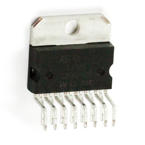
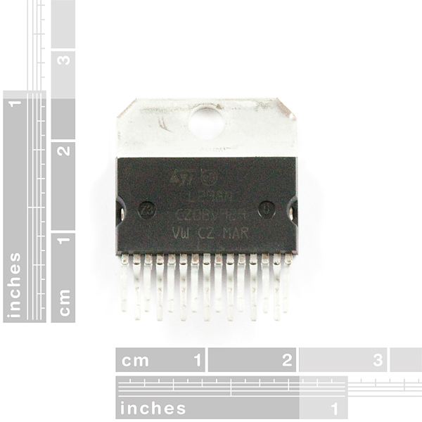
The LN298 is a high voltage, high current, dual full-bridge motor driver designed to accept standard TTL logic levels and drive inductive loads such as relays, solenoids, DC and stepping motors.
Comes in a staggered, 15-lead Multiwatt package. Check below for a breakout board.
- Operating supply voltage of up to 46V
- 4.5-7VDC logic supply voltage
- Total DC current of up to 4A
- Low saturation voltage
- Over-temperature protection
- Logical '0' input up to 1.5V (high-noise immunity)
Full-Bridge Motor Driver Dual - L298N Product Help and Resources
Core Skill: Soldering
This skill defines how difficult the soldering is on a particular product. It might be a couple simple solder joints, or require special reflow tools.
Skill Level: Rookie - The number of pins increases, and you will have to determine polarity of components and some of the components might be a bit trickier or close together. You might need solder wick or flux.
See all skill levels
Core Skill: Programming
If a board needs code or communicates somehow, you're going to need to know how to program or interface with it. The programming skill is all about communication and code.
Skill Level: Rookie - You will need a better fundamental understand of what code is, and how it works. You will be using beginner-level software and development tools like Arduino. You will be dealing directly with code, but numerous examples and libraries are available. Sensors or shields will communicate with serial or TTL.
See all skill levels
Core Skill: Electrical Prototyping
If it requires power, you need to know how much, what all the pins do, and how to hook it up. You may need to reference datasheets, schematics, and know the ins and outs of electronics.
Skill Level: Competent - You will be required to reference a datasheet or schematic to know how to use a component. Your knowledge of a datasheet will only require basic features like power requirements, pinouts, or communications type. Also, you may need a power supply that?s greater than 12V or more than 1A worth of current.
See all skill levels
Comments
Looking for answers to technical questions?
We welcome your comments and suggestions below. However, if you are looking for solutions to technical questions please see our Technical Assistance page.
Customer Reviews
5 out of 5
Based on 1 ratings:
Goodie
Beefy motor controller, handy for designing own controllers
Hooray for bulk discounts passed on to us!
Just wanted to point out to read the datasheet on these, so you aren't misled. This is a dual channel device, and each channel is rated at 2A continuous, 3A peak. You ONLY get 4A continuous, up to 6A peak IF you paralell the two channels. You can't paralell the two channels to get 8A output. Just a caveat, and a reminder to RTFM ;)
RTFM! :)
You sell the IC's but not the required diodes and hard to find low resistance, high power resistors.
I made a quick demo for this on youtube:
http://www.youtube.com/watch?v=HwFjDJD-HBQ
C code link:
http://sourceforge.net/projects/roboticscode/files/
FYI The above YouTube link is dead.
Gday Rogue1,
Your demo was very helpful, and i am interesting in doing something very similiar. I was wondering if it would be possible to get the circuit you used? Or if anyone has a similiar one it would be greatly appreciated im_4dice@hotmail.com
Thanks
Just about everyone who buys this will need some matching schottky diodes.
How about stocking either some discrete diodes, or even better an integrated bridge like an ST L6210?
The diodes aren't required for driving stepper motors are they?
The diodes are required for any inductive load, so yes you will.
The 6210 is not a bridge - it's just an array of 8 Schottky diodes. Perhaps you are thinking of the L6201 which is a single H-bridge with integrated diodes.
LMD18200 includes integrated diodes and you can get free samples :)
Yay for samples!
http://www.national.com/mpf/LM/LMD18200.html#Overview
But I'm still loyal to the LM298. I've Used them in my Mobot and a few prototypes.
Is the "peak" current synonymous with "inrush"? I have an actuator that has approximately 300 ms startup draw of ~10A, but under load is only pulling ~1.2A @ 12.6V. I don't know what kind of tolerance or suppression this package has, but those are the parameters I'm trying to accommodate.
Looks cool; but while the data sheet indeed says 46VDC, and 2A continuous per channel, it also says 25W TOTAL dissipation. If that is per device not per channel, I interpret that to mean that if you are running at (for instance) 12.5V, you get 2 amps total to work with for continuous power, not 4 amps continuous; and to get 4 amps continuous, you'd have to be running at no higher than 6V and a 46V you'd be limited to around .5A total for both channels (all of which might be just fine for your app) but definitely NOT 46V continuous at 4A (184W). But I've never even played an electrical engineer on TV, so am I misinterpreting this?
And for us unfortunate non-EE's can somebody at Sparkfun please, please translate the data sheet's note:
"The external bridge of diodes D1 to D4 is made by four fast recovery elements (trr ≤ 200 nsec) that must be chosen of a VF as low as possible at the worst case of the load current. "
into "buy this part number diode for a 12V motor between .5 and 2A, this p/n diode for 24V 4A," etc. (This is why I'm still using LMD18200s with all that integrated :-). Thanks!
It looks like the LN298 is only rated to operate at -25 C. I'd like to use it at -40 C. Is it likely to work, or can I somewhere get one of these rated for lower temps?
You'll find many parts in two temperature ranges; "commercial" and "industrial". Commercial is usually something like 0C to 70C, industrial more like -40C to 85C. (Beyond this there are automotive and military temp ratings). This part doesn't seem to come in other temp ranges, but many companies make L298 variants so you should be able to find something out there. (Also note that while operating the part itself will warm up, so this one may work fine depending on your application.)
I use 24Volt on a L298N i get 12 volts on 2 motors using 100% duty cycle.Is this normal. Shouldn't i get 24Volts for each motor output?Also if i stop one of the 2 motors i get for all the voltage to the one that is working.
Often the terminal voltage of a so-called "12 V battery" will get dragged down to 6 V (or lower!) when it's connected to a motor trying to move a heavy load. Test: If you wire both motors directly to your "24 V" power supply (replacing the L298 with some wires), do you see the same 12 V? If so, the L298 is working as designed; that is normal. (Although you may want to consider getting a higher-current power supply).
Love this chip, and it's hard to beat this price. I've written a tutorial on using this IC, with Arduino code, here.
Also, with a little bit of bending, these fit nicely into a breadboard!
do you have any products that use this chip, or similar chip, that drive larger power FETS ?
Again, hate to be "that guy", but, EAGLE footprint, please? :>
I'll be "that guy", then, and point you to the following:
When you go to add a part, in the bottom left there's a Search field. Enter "L298" there. You should get the results from the SFE libraries there :)
( It's in SparkFun-PowerIC.lbr / Device: L298 / Package: L298 or L298HEATSINK. It's also available in the st-microelectronics.lbr library. )
Does anyone know if a bi-directional transient voltage suppressor diode between the motor poles could replace the diodes?
Any chance SFE will sell the L297?
Okay, will this work with pwm signals from arduino??? I'm thinking of pulsing the enable pin.
Yes.
Do you need the 4 diodes they have in the datasheet to run a motor?
You don't need them to run the motor. You need them so that the motor's inductivity doesn't kill the L298N when you turn the motor off. So I guess that if you only run the motor once and then throw your circuit away, you don't need the diodes. Though I suspect that that's not what you're trying to do. :-P
Can I use 3V TTL with this?
And what kinda diodes do I need for this?
No on the 3v ttl. You'll need to level shift it somehow. you can use the level shifting board available here, or there are ways to use a 5v pull up with a 3.3v logic system (you'll need to understand resistor voltage dividers), and you then just use your controller chip to pull the inputs low.
Use a high voltage diode, I'd say 200v peak reverse bias. General purpose schottky or silicon diodes are fine. Fast switching would be good. you'll see very high, but very short lived currents through it.
3.3V does work. As the datasheet says "logic high minimum 2.3V".
I'm using these with a Rover 5 controlled by a 3.3V Propeller. Here's a link to the project.
Whoa, thanks for the fast response, it's me that was slow in checking my comments for replies. Is it okay to use 1000V rectifiers for the 'iodes? I've never really understood what the difference is between zeners, rectifiers, and schottkys. And how can I get me one 'o them pull-ups? I need to step up a voltage without inductors and I will only have a 3V power source.
EDIT: I will be using NPN power transistors, only need speed control. You only need one diode! :^D
Shouldn't say "Breakout board comming soon", when it's already here.
Updated. Thanks!
Puzzled. Soldered this to corresponding breakout board. Hooked up to 12 volt Battery pack as source and regulated Power supply as logic with no load. Absolute value of voltage in one direction was about 1.2 volts higher than the other on both sets of outputs (i.e. -10.5 volts vs + 9.3 volts). Is this expected or a bad chip or am I missing something?
Are you absolutely sure you didn't put it in backwards?
if I hooked up four of these in parallel will I get 16 A to drive my 16 Amps DC load (boat motor) ?
You'll want to use 5 or 6 or maybe 8. 4A is a maximum that will cause you problems if you plan on running at 100%.
^TI Text-2-Speech voice^ Now spell: YES!! IF YOU HOOK UP A 16 AMP POWER SOURCE!! I THINK!! ^end TI Text-2-Speech voice^
anyone know what the pitch is?
F-sharp
concerning the eagle package:
- check out MULTIWATT-15 and the L298 (st-microelectronics as manufacturer) in eagle >5.50+
- good news guys, glad to see this old fellow put to good use. As a source of inspiration, check out the Solarbotics compact motor driver (also using L298).
do you guys have an eagle footprint for this
Working on it. We'll post it with the breakout board when it comes out.