- Home
- Product Categories
- Arduino
- SparkFun FTDI Basic Breakout - 3.3V

SparkFun FTDI Basic Breakout - 3.3V
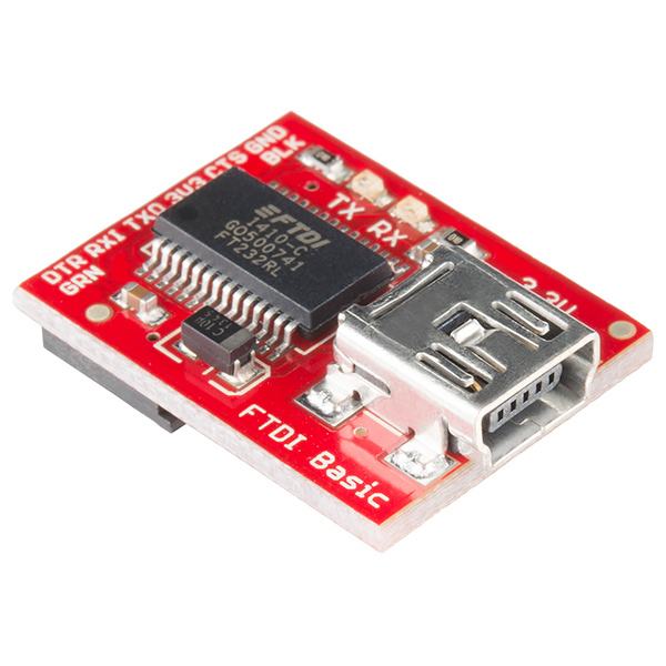
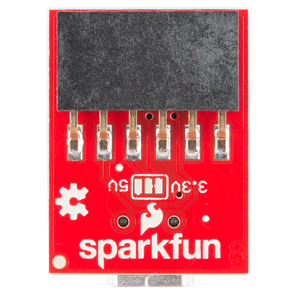
This is the newest revision of our FTDI Basic. We now use a SMD 6-pin header on the bottom, which makes it smaller and more compact. Functionality has remained the same.
This is a basic breakout board for the FTDI FT232RL USB to serial IC. The pinout of this board matches the FTDI cable to work with official Arduino and cloned 3.3V Arduino boards. It can also be used for general serial applications. The major difference with this board is that it brings out the DTR pin as opposed to the RTS pin of the FTDI cable. The DTR pin allows an Arduino target to auto-reset when a new Sketch is downloaded. This is a really nice feature to have and allows a sketch to be downloaded without having to hit the reset button. This board will auto reset any Arduino board that has the reset pin brought out to a 6-pin connector.
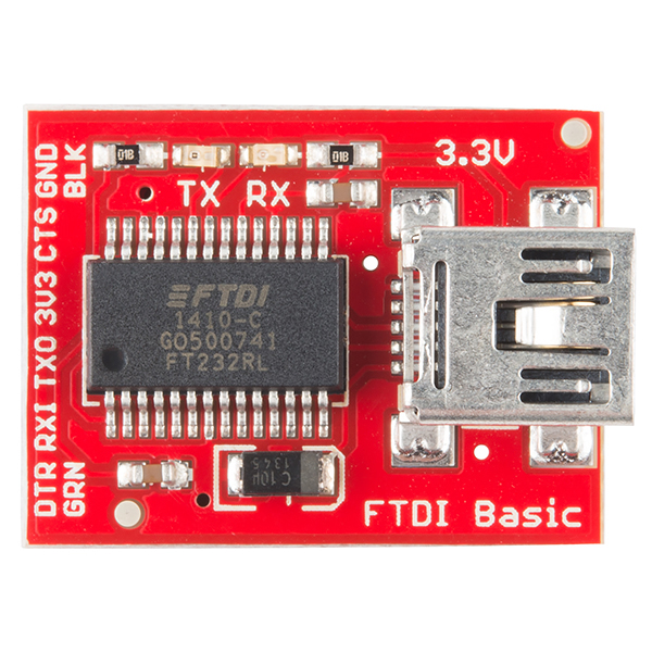
The pins labeled BLK and GRN correspond to the colored wires on the FTDI cable. The black wire on the FTDI cable is GND, green is DTR. Use these BLK and GRN pins to align the FTDI basic board with your Arduino target.
There are pros and cons to the FTDI Cable vs the FTDI Basic. This board has TX and RX LEDs that allow you to actually see serial traffic on the LEDs to verify if the board is working, but this board requires a Mini-B cable. The FTDI Cable is well protected against the elements, but is large and cannot be embedded into a project as easily. The FTDI Basic uses DTR to cause a hardware reset where the FTDI cable uses the RTS signal.
This board was designed to decrease the cost of Arduino development and increase ease of use (the auto-reset feature rocks!). Our Arduino Pro and LilyPad boards use this type of connector.
Note: We know a lot of you prefer microUSB over miniUSB. Never fear, we've got you covered! Check out our FT231X Breakout for your micro FTDI needs!
- Schematic
- Eagle Files
- Fritzing Part
- 3D Model (5V version)
- USB to serial UART Boards Hookup Guide
- How to Install FTDI Drivers
- FTDI Drivers
- GitHub Hardware Repo (Design Files)
SparkFun FTDI Basic Breakout - 3.3V Product Help and Resources
How to Work with Jumper Pads and PCB Traces
April 2, 2018
Handling PCB jumper pads and traces is an essential skill. Learn how to cut a PCB trace, add a solder jumper between pads to reroute connections, and repair a trace with the green wire method if a trace is damaged.
SparkFun USB to Serial UART Boards Hookup Guide
February 18, 2016
How to use the SparkFun FTDI based boards to program an Arduino and access another serial device over the hardware serial port, without unplugging anything!
How to Install FTDI Drivers
June 4, 2013
How to install drivers for the FTDI Basic on Windows, Mac OS X, and Linux.
Motion Controlled Wearable LED Dance Harness
January 30, 2019
Control LEDs based on your movement using an accelerometer! Make your LEDs breathe by fading in and out when laying on the floor, turn off the LEDs when moving to your side, or make the LEDs blink in a headstand!
Current Output at 3.3V
3.3V FTDIs/boards with the 3.3V jumper selected supply way, way less current than the 5V version. It's probably around sub-100mA vs 500mA+ for the 5V board. This can cause problems with radios. A tech support representative has seen it play havoc with the BC127.
Dimensions and 3D Model*
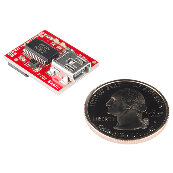
Measuring with a caliper, the board’s dimensions is about:
width = 17.91mm
length = 23.20mm (24.65mm measuring from the edge of the board to the edge of the mini-B connector sticking out)
height = 1.60mm (8.60mm measuring from the bottom header pin to the top of the mini-B connector)
There is also a 3D Model in our GitHub Repository here for the 5V FTDI [ https://github.com/sparkfun/3D_Models/tree/master/products/9716 ].
Logic Levels
The FT232R won’t be 5V-tolerant when its VCCIO is 3.3V. Driving it this way risks harm to its internal 3.3V regulator.
Converting FTDI from 3.3V to 5V
You can modify the board to make the 3.3V FTDI a 5V FTDI. The trace that connects the 3.3V pad to the center pad on the back of the 3.3V FTDI breakout board just needs to be cut with an XACTO/hobby knife. Then you need to add a solder jumper on between the 5V pad and the center pad. Here's a quick image https://drive.google.com/open?id=0B0jwgLkjMWzDcXRXVXdWMXEyUE0 . I would mark the board with a Sharpie to say 5V so you do not accidentally plug this into a 3.3V system.
Core Skill: Electrical Prototyping
If it requires power, you need to know how much, what all the pins do, and how to hook it up. You may need to reference datasheets, schematics, and know the ins and outs of electronics.
Skill Level: Rookie - You may be required to know a bit more about the component, such as orientation, or how to hook it up, in addition to power requirements. You will need to understand polarized components.
See all skill levels
Comments
Looking for answers to technical questions?
We welcome your comments and suggestions below. However, if you are looking for solutions to technical questions please see our Technical Assistance page.
Customer Reviews
4.7 out of 5
Based on 66 ratings:
8 of 8 found this helpful:
Nice board, but there's a "gotchya"
I purchased two of these boards recently, for use with an Arduino Pro Mini 3.3V. I especially like that the FTDI pins are arranged exactly the same on the Basic breakout board as they are on the Arduino; this lets me simply plug it in!
When I first used the FTDI Basic to upload a sketch, the response I got on the console was pure gibberish! A buddy and I search the web for clues as to what the problem might be. We tried everything (including a couple of different drivers and mashing the RESET button just prior to upload) short of reprogramming the FTDI chip.
In the end, we discovered that for certain boards, which may have been built in different versions, with different processor/voltage/clock-speed combinations, you must select that combination in the Arduino IDE Tools>Processor submenu. This is in ADDITION to selecting the board itself ("Pro or Pro Mini" in my case). Once you have the right board, voltage, clock speed, and processor, things will work flawlessly :-D
3 of 3 found this helpful:
Works good on OS X
Works as it should, as long as you use the FTDI drivers, not the ones built into OS X. The built-in driver has issues with leaving DTR low.
2 of 2 found this helpful:
Works Great with my MinimOSD
Super small and installs easily. I could even leave it on my quadcopter it's so light. Used it to program the on screen display module.
3 of 3 found this helpful:
Works Great
I had the 5V version of this and needed the 3.3V version for my Arduino Pro Mini boards.
4 of 4 found this helpful:
My first FTDI programmer, and a great buy!
Until now I haven't had the need for a standalone FTDI programmer. I wasn't sure exactly which one I needed, but I decided to pick up this FTDI Basic Breakout because it was recommended in the ESP8266 Thing hookup guide, which I also purchased.
My Windows 8.1 automatically installed the required drivers and my Arduino IDE was able to pick it up in just a few seconds. From there it was a simple matter of clicking a few buttons in the IDE to select the board and port, then clicking Upload; A few moments later, my ESP8266 Thing automatically reboots and runs my code without any issues.
I'm always amazed by the size of these tiny chips even when I see them online and try to imagine them in real life, they're always so much smaller than I imagined! Don't let the size fool you however; This thing works flawlessly. I just wish I had a tiny case to put this thing in, because it feels a little unsafe to unplug (my fingers might jump something, which could probably destroy the chip D:), but that's to be expected with something so tiny (tiny things are often delicate and must be handled gently). It's great that it's a bare board though because you can easily integrate it into your own case if so desired.
Serial communication was easy and works great with my ESP8266 Thing (But I forgot to buy the jumper as per the hookup guide, and must use Realterm, as the Arduino IDE keeps the Thing in bootloader mode), and I haven't had any issues or difficulties to speak of. Overall I'm very happy with my purchase and would buy it again or recommend it to friends who needed one in the future.
2 of 2 found this helpful:
Works like a charm once I figured out how to connect it for my application
Works like a charm once I figured out how to connect it for my application. I use this to send sketches to a prototype that uses a "bare" ATmega328 chip (https://www.sparkfun.com/products/10524) on a breadboard. To program the chip I hooked up the FTDI DTR pin to the RST pin via a .iuF capacitor, the FTDI RX pin to the TX pin and the FTDI TX pin to the RX pin on the ATmega328 chip. I didn't use the 3.3v pin. I used http://www.yuriystoys.com/2012/02/arduino-on-beadboard-uploading-your.html as the starting reference because I couldn't find clear instructions on SparkFun. I use the Arduino IDE to load the sketch and can monitor serial traffic just as if I were hooked up to an Arduino. The time (and potential damage) saved using this compared to swapping the ATmega328 chip back and forth from my prototype to an Arduino is well worth the cost.
1 of 1 found this helpful:
works as advertised.
No problems at all with this little guy. Worked exactly how I expected it to.
3 of 3 found this helpful:
More than one use
I have used this for the Sparkfun pro mini board (it will program the 5v board also) and other boards with FTDI headers. Notably the Adafruit trinkets (sorry sparkfun - I try everything). It also works in a pinch as a serial to UART board. Just wire it directly to any UART device (I use it to test XBees sometimes) and you can use the Arduino IDE to send serial data.
4 of 4 found this helpful:
Very nice for 3.3v TTL serial but can’t power an ESP8266
Putting the connector on the bottom is clever too. Unfortunately the power regulator on it is incapable of powering any of the ESP8266 breakout boards that I actually bought it to experiment with. For future iterations please consider a higher capacity regulator. For all other purposes it works great though.
2 of 2 found this helpful:
Works fine, just one complaint
Very easy to get this thing working.
The only problem is when converting to/from 5V/3.3V.
SJ2 is too small !
It is too hard to cut the default trace and then solder a jumper wire across the either gap. If you do this one too many times, you'll end up ruining the pads and then you have to use a jumper wire from one side of the board to the other.
Would have been MUCH better to have a horizontal jumper header to switch voltages.
What's not to love?
It does exactly what it's supposed to do. Not exactly the shiniest or most glamorous of items, but a necessary one.
Works as advertised
Works with no issues.
0 of 9 found this helpful:
Useless without a driver
Bought this to use with a Pro mini. Click on the driver link.. Start the down load.. 25 minutes later is still hasn't downloaded.. It is useless without the driver and site that you download the driver DOES NOT WORK. Without the driver it is a $15 piece of junk. If Sparkfun really wanted people to use this they would have the driver ready to download.. Not going to wait 2hrs to download a 2MB file.. That is with cable modem.. Sad.. I know I will not be buying anything more from Sparkfun.. Had nothing but problems either with shipping or getting drivers to make purchases work.. I am done..
To add to this.. Finally got it to work but working is a stretch.. It would take jumping through hoops and standing on my head to get this piece of junk to work..While connected to a MINI it would download ONCE. without unplugging and making changes and trying to download changes it would quit working. Then having to unplug and plug back into the computer and Mini about a dozen times before it would work again.... Now the computer does not even reconigize it.. A TOTAL waste of money.. DO NOT BUY THIS JUNK!
Slow down. It sounds like you are running into some localized issues. But this in not a reflection of the product or it's features.
The drivers are linked to on the official FTDI site because they release updates and revisions to the drivers from time to time. Also it's the most direct location to get a driver for every OS (Mac, Windows, and Linux)
The download link is operational from my tests.There shouldn't be any hoops, or head stands needed. Here's a video that can help, it's for Mac, but the process remains similar across different platforms. -- https://www.youtube.com/watch?v=pbmgG87eIBA
Please contact our support team if you require further assistance.
Awesome!
Simply connect to my Mac and ESP8266 Thing, and it works under Arduino IDE after quick installation for ESP8266.
Works fine
I bought this one to work on 3.3v projects. It works pretty well
Easiest Serial Interface I've used
Small, rugged, and convenient with female sockets for hooking up to CMOS. The TX and RX LEDs are more useful that I thought they would be - can see the relative timing when using multiple Breakouts. Last project used three Breakouts. Get several!
ordering process is easy. love to order from Sparkfun
Works great
Does exactly as advertised with no problems
Perfect for the Thing
I got this to program my Esp8266 Thing. I had put female headers on my Thing so I used some male headers to connect the FTDI to the Thing. I was able to upload the example sketches straight away with no problems. I have not used any other FTDI parts so I can't compare them, but this one seems to do the job!
Must have device
Small and compact much easier to store than versions with the cable built in. Love that it can be modified for 5v use.
Good product
The board works as advertised. I am able to program my Arduino based project without having an on-board USB chip.
Great parallel to the 5V FTDI basic
Great board for adding programmability to a 3.3V microcontroller from a host computer. Whats nice is that if you're in a jam, you can turn this guy into a 5V breakout or vice versa. I did this by looking at the three solder pads on the back of the board and severing the center pad wire to the "3.3v" side. On my board, the silk screen on the board seemed like pretty serious business, because I couldn't sever the connection using a razor blade just on the pcb, so I just clipped the 3.3V power line header, and soldered a little piece of wire to the 5V solder pad on the back. A little ugly, but ended up being a heck of a lot easier/faster than digging that razor blade into the pcb, and totally still works solid but at 5V! Obviously, check the wiring diagram to make sure you understand what you're doing before attempting, but this is possible.
Performs as expected
No issues.
Needed tech support: my fault
I bought this along with a Pro Mini. I soldered a header to the Mini, and plugged it in. I get a green light on the Mini, but on uploading a sketch, the IDE gives error "avrdude: stk500_getsync(): not in sync: resp=0x00" And tx and rx never blink. I searched for the error, and got a lot of "solutions," some of which I tried without luck.
Update: tech support was able to help me find a port to use. My Windows system still doesn't show an FTDI device, but the IDE finds it. It works now.
I have the board and com set properly. I can successfully upload to a Mega, so the drivers are okay.
Hmmm, we rarely see problems with this board. I would suggest contacting our tech support team, they should have no problem helping you fix your issues, or, if it's a faulty board, getting you a replacement.
works great, but...
This interface works great, it's easy to install, but sometimes it can't connect to the comm port the first time. It takes two attempts to get a connection. Also, the LEDs that show the status and power end up being on the bottom of the board. This makes it tough to see the status of the programming and download.
Blindingly Simple on Win 10
Bought it to program Arduino Pro Mini. Plugged everything together and it simply worked -- no monkeying around required.
Works fine, but needs the right USB cable
I initially had problems with using the board. I found that the shield of the USB connector on the board is not grounded on the board and the cable that I initially used only provides ground over the shield. I am not sure whether that cable is actually broken or just a non-standard product. Anyway, after using a cable with an internal ground conductor everything works fine. By the way, the "bad "cable works fine other products.
It just works
I had purchased a more expensive FTDI breakout that could be set to 3.3 or 5V via a solderable jumper. It came set for 5V and I had to desolder and resolder to set it to 3.3V. I tried and it didn't work, so I bought this one instead. No jumper, it just works.
Very good
I did exactly what I want it to.
I use it to program ESP8266
I just jumper wires from this device to standard ESP8266 modules, and am able to download code directly from the Arduino IDE. It's very compact.
You know, Sparkfun should come up with an ESP8266 programming "jig" based around this board that uses DTR/RTS to control gpio 1 and the reset signal.
Handy board
Works well, excellent!
Makes Programming Arduino Pro Boards Simple
Arduino Pro has no USB connectivity on board. With this, I don't need it. I'm using an old WindowsXP netbook with FTDI drivers previously installed for another device. XP recognised this basic breakout, loaded the drivers and I was uploading to Arduino Pros in minutes from opening the box.
Great!
Great device, great delivery time. It works just perfect according with the details provided.
Breakout
The breakout works fine. I bought it along with the ad8232 heart pcb. The processing sketch to the heart tracing is filled with syntax errors. Your better off typing up your own processing sketch. Good job sparkfun. Your breakout is fine. All your hardware is in excellent condition. I wish I could say the same about your sketches.
Works as described
Worked well with my computer and haven't had any problems whatsoever. Great product and works as promised.
FTDI Basic
I found the board very easy to use with the Mini Pro, I have some neat ideas for some Halloween decorations and the small footprints will make things easier.
Indispensable
I have bought many FTDI Basics, I use them for all sorts of projects. I wish there was a 1.8V version.
Great little FTDI, works as expected.
I bought this to flash the now quite popular Sonoff WiFi home automation switches, which use an ESP8266 chip and provide only a raw programming header with no USB support.
Although I maybe, probably, possibly should have bought the larger version of this just for ease of use, it works perfectly.
The product photos don't show the pinout edge of the board, which is indeed a female header pin style of plug (into which you can insert common jumpers or a male header).
Ah yes ,your product programmed a 5volt arduino mini pro I used with Jameco thermistor kit( Kitpro #2184579.After 5 hrs. assembly on circuit board and 5hrs attempting to program kit worked .Temperature has only 4% error due t10k resistor being 400 ohms low. Though theSpark Fun FTDI Basic Breakout-3.3v was lower voltage (my bad) it programmed well.The kit works fine. Thank You
Works as expected
Because it uses FTDI silicon, it plays nice with FTDI drivers and utilities. I like the ability to change the voltage between 3.3V & 5.0V which you can't do with a cable (though a jumper option would be nice). My only nit-pick is the LEDs are too dim to be easily seen in normal office lighting.
Solid performer
It's suitable for numerous uses, but I use it with the Arduino IDE and the SparkFun ESP8266 Thing. It's reliable and trouble-free.
Works great with Linux
I've been a long time Fedora user and these little boards work great out of the box with minicom and my ESP-01's. A little udev magic helps me map the ttyUSB device to a simpler name: ttyUSBFTDI, though that isn't necessary.
SUBSYSTEMS=="usb", ATTRS{idVendor}=="0403", ATTRS{idProduct}=="6001", GROUP="mjhammel", MODE="0660", SYMLINK+="ttyUSBFTDI"
Simple to use for a beginner
My 12yr old son used this for his first Redboard project and had zero issues.
He designed a padlock with a fingerprint ID for his 7th grade STEM class. The FTDI was used to initially connect the fingerprint scanner to the computer, run their demo software, and store the fingerprint.
Great product and very simple to use.
works fine
purchased this for my arduino pro mini and programming went smooth. the usb is a tight fit and required some decent force to snap it in. i wish it was cheaper... the arduino pro mini cost $10 but this costs about $15.
Good Product.
It's a good converter.
Very useful
I already have one FTDI - USB cable but that's not enough when trying to debug sketches across multiple ESP8266s. Personally I would have preferred a micro USB connector since that's what most of my cables are, but I do still have enough mini USBs to get everything plugged in.
FTDI 3V connetion
I needed the FTDI breakout to interface with the FIO Arduino and it work just fine. I installed a header to make the connection simpler only thing is I had to be careful on the orientation as it can be install backwards and damage the parts.
All an every SparkFun projects are better then GREAT
Watch thire videos . Reply if necessary. !
Does The Job Elegantly
A nice, simple solution for programming Pro Mini and related boards without the onboard USB interface. Note this is a 3.3v unit, which is exactly what you need for 3.3v Arduino variants. Get the 5v version for 5v Arduinos!
Great Product
I have purchased quite a few of these, and haven't had any trouble. They are easy to use. The labels RXI and TXO are a great feature to limit connecting the lines backwards. The only downside is not having an easy way to switch between 3.3V and 5V. However, I primarily only use 3.3V.
Perfect
Needed a 3.3V FTDI interface to update my Jumper T16 OpenTx firmware and add a bootloader. Worked perfectly with my Win10 2004 system.
Works perfectly!
No need to fidget with wires. Just connect and you are done. Excellent for beginners.
Works well, simple and useful
Works well. I wired by hand and had a mistake that wasted an hour :/ maybe it is worth buying a pre-made cable assembly for the UART portion.
Can't live without it!
This little power supply & communication board for the Arduino is well made and very reliable. I use several of them every day and never had a problem. Very convenient!
0 of 2 found this helpful:
Have not used it yet.
i'm in UK. Will be using it when I return.
Perfectly reliable
Simple, no-frills, works better than an FTDI cable I had been using in the past—especially when it comes to resetting my Arduino for uploads. I'm happy as a clam with it.
Works reliably (with a fix)
It works flawlessly once you get the drivers installed, no complaints as far as functionality goes.
Mine did come with a very poor soldering job; the USB connector snapped right off the board, and you could see the legs had barely any solder on them. The surface mount pins were also weak and hard to reach. Once I fiddled around with it and resoldered the USB connector it worked as expected.
Sorry to hear that your device had some subpar soldering. We try to inspect and test every board we release. Some times a bad unit slips past our processes though. If you have this issue in the future, let us know and we'll be happy to help resolve the issue.
Very practical
Helps with programming and comunication
Short lived
Using the FTDI breakout for very basic tasks of loading and communicating with the Pro mini (3.3v) works well. Of course, to be useful, other devices, displays, etc. need to be hung off of the Pro. When hanging additional components onto the Pro one has to watch the current draw. This is particularly true with displays, so my circuit leaves open the 3.3V output from the FTDI to the Pro and display and power is supplied via a separate circuit to both of them. The FTDI seems to be very sensitive to either power sequencing or leakage paths since I have had two of them stop working after maybe 5-10 power-up-down sequences. At that point the computer will attempt to upload the sketch and just hang there waiting for a handshake. An improvement to this product would be to include a separate voltage regulator capable of handling more current so that during development everything is powered in-situ. The battery system can be applied separately after the software is complete and the FTDI is disconnected. Notice should also be given to customers that the FTDI is sensitive to this issue.
The FT232RL datasheet discusses different power options and points out that for devices that require 100-500ma should be setup specifically in a max power mode. We do not set this up by default. However, if you need to use the device in this way, there is description of how to change this in the datasheet.
does it provide any USB noise isolation ?
I bought this FTDI Basic with Mini-B Cable and it work properly.
Not sure why there are two separate versions of these FTDIs. As has been previously pointed out, there is a 3.3V pad and a 5V pad, with the output in the center. The only difference between the FTDIs seem to be where the trace is coming from.
I had bought a 3.3V FTDI and I need it to supply power to a 5V Arduino Pro Mini. Per bboyho's post, I cut the 3.3V trace and created a solder bridge between the 5V and center pads. It worked fine, but I still needed 3.3V. So, I mounted a small switch to the FTDI and did some really fine soldering to the pads. It's not pretty but it works like a charm.
Image
I have one of these and it has worked great ever since I got it a year or two ago, but all of a sudden it just stopped working. Windows is saying the device is not recognized and giving error code 43. I have tried reinstalling drivers and restarting my computer but nothing seems to work. Is anyone else having these issues?
What is the purpose of the 5V-3.3V solder pads on the back of the board ? Does it change the voltage level of the I/Os ? What happens if i solder the 5V pad ? (since the board is supposed to be a 3.3V board ?! I am confused an no explanation found on this site)
I noticed this was brought up a few times. There is a small pad on the back to select the voltage. There is a very tiny trace between 3v and the center pad. I cut mine and soldered a 3 pin jumper to the pad. Now I have 5v and 3v selectable! Just be sure to select the right voltage before uploading. I wonder why SF does not include an SMD selector switch?
To point out an error in the description: "This board was designed to decrease the cost of Arduino development and increase ease use" Shouldn't it be ease of use?
Why isn?t the header aligned with the edge of the board like the 5V?
Make sure you install the FTDI drivers from FTDIChip.com if you are using OS X Yosemite (maybe earlier versions also, unsure). The built-in OS X driver leaves DTR low after the first connect, which is super annoying.
oops. This product won't work on the beagle bone black, the ftdi-arranged sip headers for the serial out are tooo close to the 2 row pin socket header for the part to fit.
Why are there no instructions on how to connect this to an Arduino Pro Mini? I'm assuming I just connect the end of the mini to the plugs on this board. I hope the pins are correct!
Later response, but for anyone else who is wondering, you can connect this directly with the Arduino Pro Mini 3.3V and the pins line up. I suggest getting a 6 pin right angle male header or Break Away Male Headers - Right Angle to solder to your Arduino Pro Mini.
I just got one via a local store. On the top it says 3.3 V but on the bottom the trace is set to 5 V.
What is it? 5 V or 3.3?
It might be a 5V. the easiest way to tell is to plug it in and measure from VCC to GND.
Thanks! It's 5 V.
Another thing I could not find out here is how to connect an Arduino bootloaded MCU to the DTR.
After a little bit of google search I found out that you need to put a 100 nF capacitor between DTR and the reset pin (pin 1 in case of a atmega328). In my case, just connecting reset and DTR did not work.
Maybe you could put this information into the description.
There are thousands of uses for this board. If you look at the breadboard Arduino kit, we have it hooked up this way.
Can you cut the solder bridge on the back and make this unit 5v?
I am under the impression that if you cut the 3.3v bridge and re-wire to 5v you can convert this unit as such.
So...how do I use this on linux? It doesn't create a /dev device, or show up in the Arduino IDE, or even show up in lsusb.
I would like to introduce you to the scm which is an alternative library to rxtx/javaxcomm for serial port communication. I have tested both CP2101 and FT232R from spark fun successfully. Wiki : http://www.embeddedunveiled.com/ Repository : https://github.com/RishiGupta12/serial-communication-manager Video : https://www.youtube.com/watch?v=fYLQbelGunQ
It supports RS-232 control signals handshaking, monitoring and has been ported to Linux, MAC, Solaris and Windows operating system. It is consistent, portable, efficient, reliable, testable, extensible, modifiable, scalable library.
Do you have CAD models of this board (STEP preferably)? Or at least a PDF of a dimensioned drawing?
Can anyone tell me if this uses "Genuine" FTDI chips? I just read that some of the clones are being "bricked" by the newest FTDI drivers.
http://arstechnica.com/information-technology/2014/10/windows-update-drivers-bricking-usb-serial-chips-beloved-of-hardware-hackers/
Thanks! - Dan
Yes, we actually just posted on the front page an article talking about this. All of our FTDI chips should be legit.
Is there a guide available that details how to actually use this board? All I have found so far is the FT232RL datasheet. It's not really helping me program my MCU to be able to talk to this guy.
I use this to send sketches to a prototype that uses a “bare” ATmega328 chip (https://www.sparkfun.com/products/10524) on a breadboard. To program the chip I hooked up the FTDI DTR pin to the RST pin via a .iuF capacitor, the FTDI RX pin to the TX pin and the FTDI TX pin to the RX pin on the ATmega328 chip. I didn’t use the 3.3v pin. I used http://www.yuriystoys.com/2012/02/arduino-on-beadboard-uploading-your.html as the starting reference because I couldn’t find clear instructions on SparkFun. I use the Arduino IDE to load the sketch and can monitor serial traffic just as if I were hooked up to an Arduino.
I get frequent crashes on OS X when I plug this in to my Arduino Pro Mini. I am running Mac OS X 10.9.2 and Arduino IDE 1.0.5. I do not have this problem with my Uno or with RAMPS (I think that uses a Mega). Has anybody else experienced this issue? Does anybody have a solution?
I just received 2 FTDI basics for 5V and 3.3V. I'm using it to communicate with an ATTint4313. The 5V version works fine when the chip is running at 8MHz. Windows loads the driver (Windows bell sound) and I can see text in a Putty window. Perfect. However, if I switch to 3.3V and try to use the 3V3 version. Windows doesn't even recognize that I've plugged anything in. Am I missing something here?
It turns out that it was a bad USB cable. The 5V version only worked when I connected 5V pin to the 5V rail on my breadboard. The 3V3 version didn't work. However, since I've switched cables, both work without connecting the 5V (or 3V3) pin to the breadboard power rail. Problem solved.
I am trying to run the FTDI with my ATMEGA328 (32 QFN) running at 3.3V, the internal fuses have been set for no brownout and internal clock. The FTDI seems to pull down the 3.3 TX and no data streams, is there an internal level shifter, or is this actually meant for 5V devices?
I resolved the issue, the bootloader board I made had the MISO/MOSI pins still powered. This caused it to not fully cycle when the 3.3V line was disconnected, but when the system was disconnected the ATMEGA328 was able to properly power down.
There really should be an option of connecting 5V ( unregulated 500mA USB ) to the FTDI header and keeping the VCCIO at 3.3V. This would make the circuit identical to the FTDI 3V cable. I don't understand the point of providing the current limited 3V ( that is only intended on driving VCCIO ) to the header. One great feature of the FTDI pinout is providing the 500mA at 5V USB raw for powering a projects local LDOs to 3.3V on down. This board only supports that if using 5V IO. According to the FTDI232R spec, the 3V3OUT can only provide 50mA. Plugging this 3V board into an FTDI compatible circuit requiring up to 500mA will certainly cause problems for the FTDI232R. I bought one of these and now realize I must hack it up to use it without damaging it.
The 5v model says it can do 3.3v, in the official description, but not vice versa. Is the flip in this direction going to be possible?
Also, could one use a logic level converter to use a single FTDI with arduinos of both voltages?
I am trying to use the FTDI basic to read the flash of an Ateml ATmega328p processor using the avrdude but I can't find the correct type of programmer for this case, any help please.
I'm just getting into this electronics stuff, so this may sound like a stupid question...Is this designed so you can hook up a pro mini to it, download your sketch, then disconnect? In other words, if i buy 3 pro minis, I only need one of these?
You are correct! I recommend you install a right angle header, 6 pins in length on the end of each of the pro minis. This will keep it low-profile. Then all you have to do is slide on the FTDI to reprogram the pro mini. Welcome to hardware! And let us know if you have any other questions.
does this breakout board comes with a free mini B cable? can use other cable instead of mini B?
Would this be appropriate for connecting an external USB modem to an Arduino?
Getting junk/encoded data back when using the serial monitor from an Arduino Pro Mini via the FTDI Breakout. While listening to a rotary encoder, rather then getting back "FWD" or "BKD", I'm receiving stuff like this: "û!@óá@óý" Course the flavor of garbage depends on the baud rate in the program and monitor. I'd tried many, assuming the breakout only works at certain rates. I've updated my FTDI drivers and am listening to tty.usbserial.AD01TONV. Help!?
You may have the wrong baud rate selected for the serial monitor.
any suggestions?, Im using an arduino mega as a hydrolic controll system, but it also controls and reads a heater and temp sensor, the temp sensor is the issue as it out puts rs232, i have an rs232 to usb converter. Im hoping that I can use the ftdi basic as the intermediary but the HH42 requires an RTS, so the problem im having is the thermometer doesnt know it is pluged in to the ftdi for lack of this signal. any help would be apreciated
Hi all
I bought the FTDI BASIC BOARD 3.3V to program the arduino pro mini.
Which drives do i use with xp OS.There are only two But don't know which drives to downpoad to my PC.
Would SFE ever consider making a breakout like this that had DTR and RTS (instead of CTS)? That would allow for 2 digital outputs from the PC, which is great for bootloaders that need test and reset such as the MSP430.
We already do! BOB-00718 breaks out all of the FTDI chip's pins; I use this one a lot for programming ARM processors with Flash Magic.
When do you guys expect to have these back in stock ? Thanks.
Can this be used with the Arduino Pro Mini 5V just as the 3.3V?
The problem I have with this USB breakout is the VCCIO pin on the FT232RL is left floating. This means the interface signal are at 3.3V. The VCCIO pin should be jump-able to either 5V or 3.3V. Will this be corrected on a later version?
Have a look at the schematic again. VCCIO is connected to a net labeled 'POWER'. This net is connected to either 5V or 3.3V through the selectable jumper. Depending on what you select the IO pins will operate correctly at 5V or 3.3V.
Can I use this to program/configure Xbee Series 1 modules instead of buying the USB Explorer USB board?
I'd love to see a version of this with a micro-usb connector.
Great feedback! I will pass it along.
If you are using one of these boards on Linux and having "permission denied" even though you ought to have read/write permissions for the relevant TTY file, see this bug :
bug 586751
Basically, some versions of udev misidentify every device that uses an FTDI chip as one particular device, and attaches the tty to the powerd daemon.
To fix the problem, you just need to comment out the udev rule for that device (see the bug). Or, wait until your distro pushes udev with the updated rules.
Does this charge the battery when you plug this FTDI Basic Breakout into the Arduino Pro where the battery is attached? My assumption would be Yes, but I rather get confirmation to be sure.
Do you sell the SMD female headers, like the one on the FTDI Basic Breakout?
At the moment we don't. I can suggest it to our product research department. digikey.com or mouser.com should have them. :)
Your Schematic is showing it's the jumper is wired for 5 V not 3.3V even thought it says 3.3 V right below the jumper in the schematic
Thanks for pointing this out. The device is actually routed to 3.3V. There is an error in the schematic, but not in the physical product. We will get this document corrected. Thanks!
Does this work with XBee Explorer Regulated (WRL-09132) directly?
No, this is designed to mate up with an Arduino, which has TX and RX reversed. This has the same pinout as the explorer regulated, which means output will be going into output and input into input. They won't talk. What you want is a Xbee explorer USB which is an FTDI basic combined with an explorer regulated.
Here
What is the temperature operating range of this device?
I haven't tested the temperature operating range of the FTDI basic, but the FT232RL ic operating temperature range is -40°C to 85°C. Hope that helps!
Dimensions Shown in the images are not correct.
Actual dimensions are: 18x22 mm
Actually, it measures 23.5 x 15.5mm
I'll get the pictures updated, thanks.
Is this board compatible with the ArduIMU?
FYI:
The schematic shows the 3.3v board wired for 5v while the Eagle files shows the 3.3v jumper set. Might be confusing to some people.
Are the IO pins 5v tolerant? What is the max current it can supply?
There is something I miss. You say:
"The major difference with this board is that it brings out the DTR pin as opposed to the RTS pin of the FTDI cable. The DTR pin allows an Arduino target to auto-reset when a new Sketch is downloaded. This is a really nice feature to have and allows a sketch to be downloaded without having to hit the reset button."
But really this pcb behaves reverse and I MUST PUSH reset button in order to download a new Sketch. I've tested this with several Arduino boards with the same result.
Can you have a look at this????
EngGirl<br />
<br />
As such?<br />
<br />
XBee Explorer USB<br />
http://www.sparkfun.com/products/8687
I know this is probably an odd question but is it possible to configure an XBee with this???
Can you program an XBEE with this as well?
yes guys absolutely, you can program xbee with it. actually you can also program ur xbee with Arduino MCU just connect GND to RESET and ur good to go
Have you thought about selling this in kit form? It would be good for sufrace mount soldering practice, and you can't have too many of these.
Is it possible to use this board with 4d uOLEDs instead of the ?USB-CE5 ? Thanks for any advice.
It is possible to do such. After reviewing the datasheets, it does state near the end that the ftdi from 4d is a 3.3v device