SparkFun XBee Explorer USB
This is a simple to use, USB to serial base unit for the Digi XBee line. This unit works with all XBee modules including the Series 1 and Series 2.5, stand
Product Overview
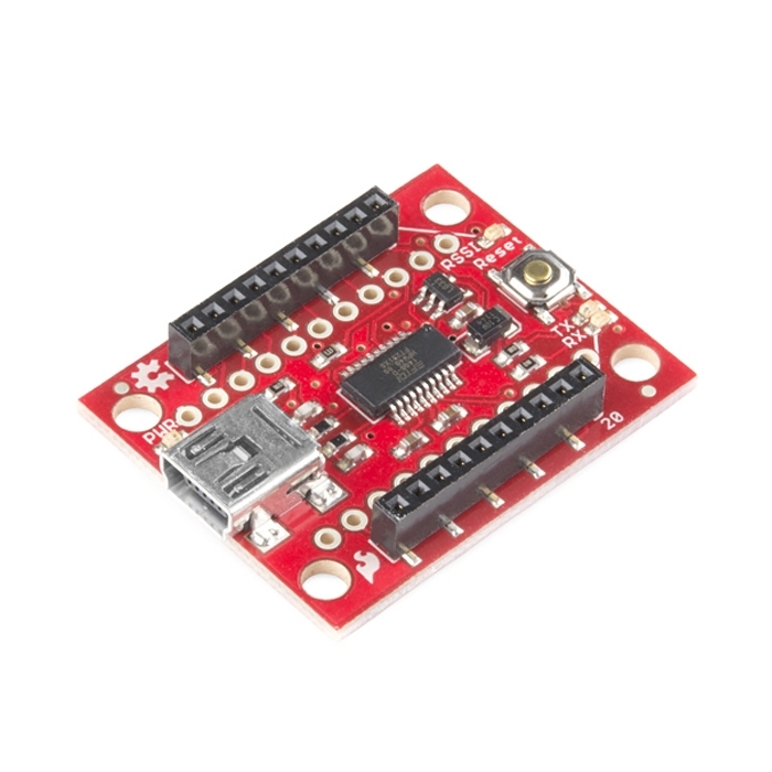
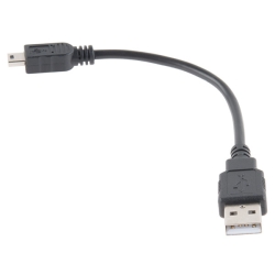
This is a simple to use, USB to serial base unit for the Digi XBee line. This unit works with all XBee modules including the Series 1 and Series 2.5, standard and Pro version. Plug the unit into the XBee Explorer, attach a mini USB cable, and you will have direct access to the serial and programming pins on the XBee unit.
The highlight of this board is an FT231X USB-to-Serial converter. That’s what translates data between your computer and the XBee. There’s also a reset button, and a voltage regulator to supply the XBee with plenty of power. In addition, there are four LEDs that’ll help if you ever need to debug your XBee: RX, TX, RSSI (signal-strength indicator), and power indicator.
This board also breaks out each of the XBee’s I/O pins to a pair of breadboard-compatible headers. So if you want to make use of the XBee’s extended functionality, you can solder some header pins into those, or even just solder some wire.
Not sure which XBee module or accessory is right for you? Check out our XBee Buying Guide!
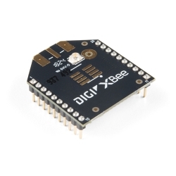
Note: There is no XBee included with this Explorer USB. Check the Recommended Products section below for different options.
Note: This board cannot source the power required for the Cellular XBee line. It will only work with the 802.15.4 variants.


Documentation
Customer Reviews

Stock and Customer Discounts
Available Discounts
- $31.02 | 10+ units
- $29.39 | 25+ units
- $27.75 | 100+ units