Basic Servo Control for Beginners
 El Duderino
 Servo Control with the SparkFun Servo Trigger
Our first example demonstrates how to move a servo motor using the SparkFun Servo Trigger. This example requires no coding or computer connection but assembling it as recommended involves some through-hole soldering. If you are not familiar with soldering through-hole components, take a look at our How to Solder: Through-Hole Soldering tutorial to get started.
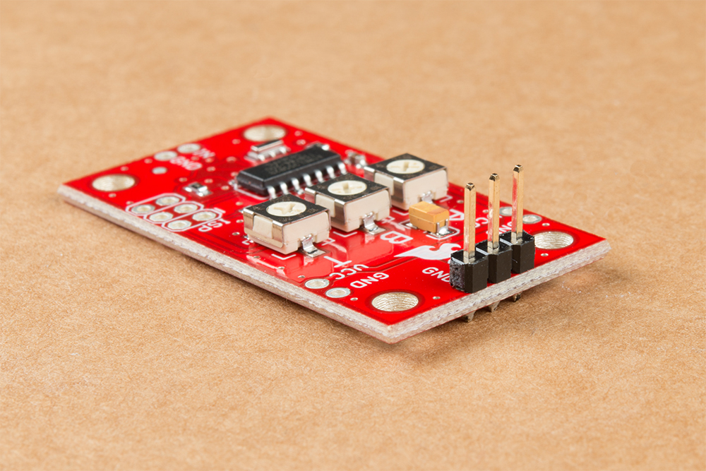
The Servo Trigger works by using pre-loaded firmware on the board to interpret the position of the three potentiometers on the board. The potentiometers determine the start and stop positions of the servo (labeled "A" and "B") as well as how long it takes for the servo to travel from the start and stop positions (labeled "T"). The movement sequence is initiated by connecting the IN and GND pins together. In this example, we are going to use this Concave Button to create that connection.
This is just a brief overview of how the SparkFun Servo Trigger works. For a full overview of the board and how to use it, take a look at our Hookup Guide for it.
Servo Trigger Hookup Guide
March 26, 2015
Required Materials
To follow along with this example, you will need the materials in the Wishlist below. Feel free to add or remove items to your cart depending on what parts you already have or which servo you would like to use.
Required Tools
Along with the parts listed above, we recommend the following tools and materials to assemble your circuit:


Hardware Hookup
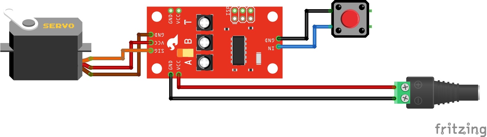
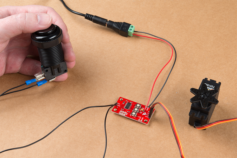
You will need to make the following connection. Below is a Fritzing diagram of the parts connected to the Servo Trigger. We'll go through step by step showing how to connect the components together.
Once you have all of your materials and tools together it's time to start assembling your circuit. We will start by soldering to the servo pins on the Servo Trigger. Clip off three pins from your chosen breakaway header and solder it to the row of 3 pins for the servo labeled SIG, VCC and GND. Using a male header lets us easily connect and disconnect our servo motor from the trigger board. If your wire harness for your servo is too short you can lengthen it with this servo extension cable.
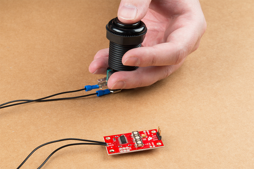
Next up is the connections to our button. Take your two spade connectors and solder the bare wire end to the IN and GND pins on the opposite side of the Servo Trigger from your servo connection. You can substitute other materials here to connect your control input (ie pushbutton) like hook-up wire if you want to use a different button that does not have a microswitch. Once that is soldered into place, connect the spade connector end of that wire soldered to IN to the connector labeled NO and the other spade connector soldered to GND to the COM connector on your button's microswitch.
The last part of assembling our circuit is making the connections for the power supply. You can solder headers into place and use jumper wires to make the connections to your power supply similar to the servo connection but since this is connected directly to our power supply, we're going to solder wire directly to the VCC and GND pins on the side of the Servo Trigger for a secure connection.
We want two lengths of wire for the Power and Ground inputs from our power supply. Strip one end of each wire and solder it to the VCC and GND pins on the side of the Servo Trigger as the photo below demonstrates.
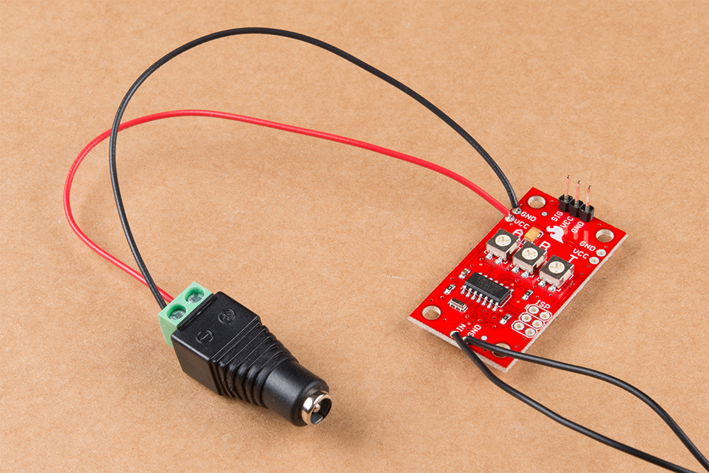
Now, when using the DC Barrel Jack Adapter, strip away a some of the insulation on the other end of your wires now soldered to the Servo Trigger, insert them into the screw terminal on the end of the adapter and secure them into place using a screwdriver. Make sure to match the wire soldered to the VCC pin with the terminal labeled "+ and the other wire soldered to GND with the one labeled "-".
With everything soldered to your Servo Trigger and your button and servo connected (assuming you have not done so already), connect your power supply and press the button. You should see your servo sweep from one side to the other. Try adjusting the three potentiometers on your Servo Trigger to switch the direction, movement arc and movement time for your servo.
Troubleshooting Tips
Servo Not Moving or Powering On
The most common source of any problems with the servo not moving or not reacting to the button press will be a bad solder joint. If your servo is not powering up or is not moving when you press your button, check that your solder connections are completely connecting the pin or wire to the solder pad and the wires or solder joints are not touching each other. Also, make sure your power supply is plugged in fully to the DC Barrel Jack Adapter and your wall socket and is providing enough voltage to power the servo and the Servo Trigger. For tips on reworking bad solder joints, take a look at our Troubleshooting Tips Guide.
Erratic Movement
This may be caused by the potentiometers set beyond the servo's pulse range or possibly by having the button wired backward. Try adjusting the "A" and "B" potentiometers to fix erratic movement. If your servo is moving immediately when power is applied and then reacting unexpectedly to your button press, you may have one of your wires for the button connected incorrectly. Check to make sure you have the IN pin tied to the NO connector and the GND pin tied to the COM connector on your button.