Galileo Experiment Guide
This Tutorial is Retired!
This tutorial covers concepts or technologies that are no longer current. It's still here for you to read and enjoy, but may not be as useful as our newest tutorials.
 HelloTechie
 SIK Galileo - Part 6: Reading a Photoresistor
Introduction
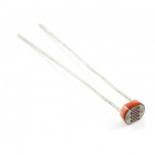
In Circuit 2, you got to use a potentiometer, which varies resistance based on the twisting of a knob. In this circuit, you’ll be using a photoresistor, which changes resistance based on how much light the sensor receives. Since the Galileo can’t directly interpret resistance (rather, it reads voltage), we need to use a voltage divider to use our photoresistor. This voltage divider will output a high voltage when it is getting a lot of light and a low voltage when little or no light is present.
Parts Needed
You will need the following parts:
- 1x Breadboard
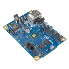
- 1x Galileo
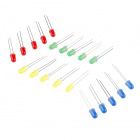
- 1x LED
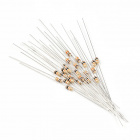
- 1x 330Ω Resistor
- 6x Jumper Wires
- 1x Photoresistor
- 1x 10k Resistor
If you are following through all of the SIK Galileo tutorials we suggest using these parts:


View the SparkFun Inventor's Kit for Galileo wishlist, to see the parts needed to go through the all the experiments.
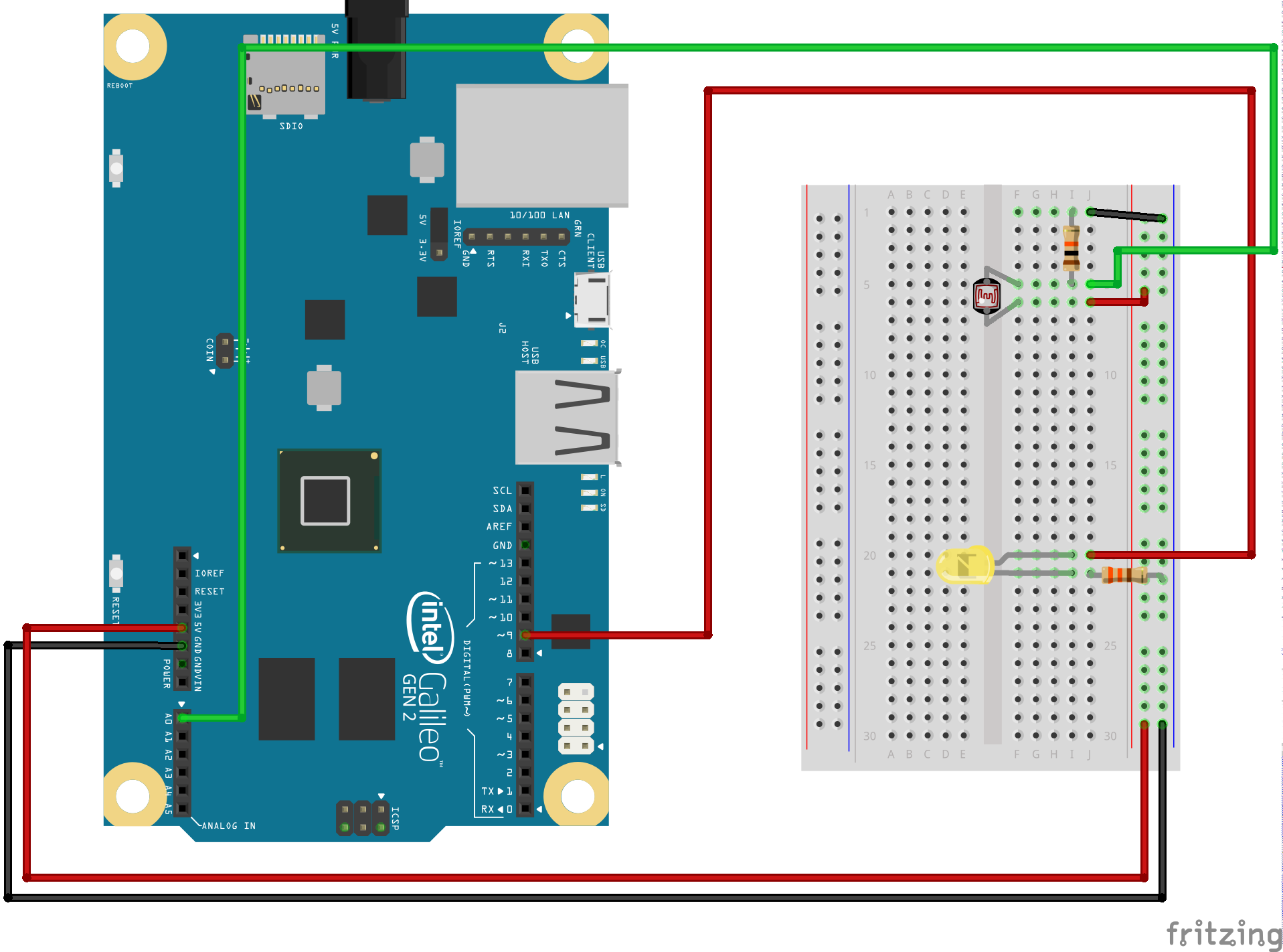
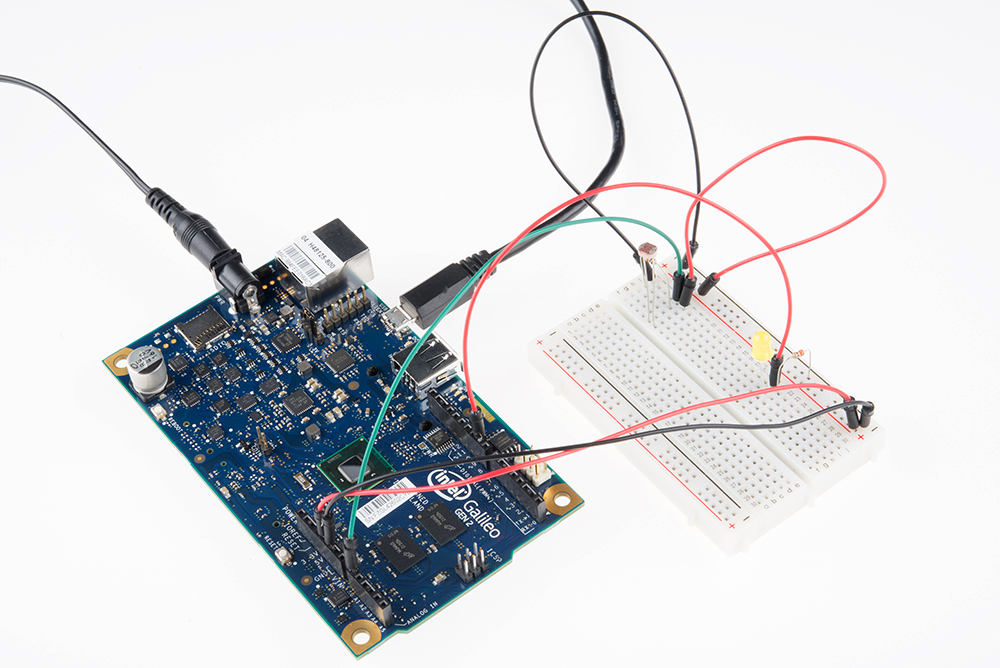
Hardware Hookup
Ready to start hooking everything up? Check out the Fritzing diagram below, to see how everything is connected. Pay special attention to the component’s markings indicating how to place it on the breadboard. Polarized components can only be connected to a circuit in one direction.
Fritzing Diagram
Code To Note
lightLevel = map(lightLevel, 0, 1023, 0, 255);
Parameters
map(value, fromLow, fromHigh, toLow, toHigh)
value: the number to map
fromLow: the lower bound of the value's current range
fromHigh: the upper bound of the value's current range
toLow: the lower bound of the value's target range
toHigh: the upper bound of the value's target range
When we read an analog signal using analogRead(), it will be a number from 0 to 1023. But when we want to drive a PWM pin using analogWrite(), it wants a number from 0 to 255. We can "squeeze" the larger range into the smaller range using the map() function.
See Arduino's map reference page for more info.
lightLevel = constrain(lightLevel, 0, 255);
Parameters
constrain(x, a, b)
x: the number to constrain, all data types
a: the lower end of the range, all data types
b: the upper end of the range, all data types
Because map() could still return numbers outside the "to" range, we'll also use a function called constrain() that will "clip" numbers into a range. If the number is outside the range, it will make it the largest or smallest number. If it is within the range, it will stay the same.
See Arduino's constrain reference page for more info.
**Copy and paste the following code into the Arduino IDE. Hit upload and see what happens! **
language:cpp
/*
SparkFun Inventor's Kit Galileo
Example sketch 06

PHOTO RESISTOR

  Use a photoresistor (light sensor) to control the brightness
  of a LED.

Hardware connections:

  Photo resistor:

    Connect one side of the photoresistor to 5 Volts (5V).
    Connect the other side of the photoresistor to ANALOG pin 0.
    Connect a 10K resistor between ANALOG pin 0 and GND.

    This creates a voltage divider, with the photoresistor one
    of the two resistors. The output of the voltage divider
    (connected to A0) will vary with the light level.

  LED:

    Connect the positive side (long leg) of the LED to
    digital pin 9. (To vary the brightness, this pin must
    support PWM, which is indicated by "~" or "PWM" on the
    Arduino itself.)

    Connect the negative side of the LED (short leg) to a
    330 Ohm resistor.

    Connect the other side of the resistor to GND.

This sketch was written by SparkFun Electronics,
with lots of help from the Arduino community.
This code is completely free for any use.
Visit http://learn.sparkfun.com/products/2 for SIK information.
Visit http://www.arduino.cc to learn about the Arduino.

Version 2.0 6/2012 MDG
*/


// As usual, we'll create constants to name the pins we're using.
// This will make it easier to follow the code below.

const int sensorPin = 0;
const int ledPin = 9;

// We'll also set up some global variables for the light level:

int lightLevel, high = 0, low = 1023;


void setup()
{
  // We'll set up the LED pin to be an output.
  // (We don't need to do anything special to use the analog input.)

  pinMode(ledPin, OUTPUT);
}


void loop()
{
  // Just as we've done in the past, we'll use the analogRead()
  // function to measure the voltage coming from the photoresistor
  // resistor pair. This number can range between 0 (0 Volts) and
  // 1023 (5 Volts), but this circuit will have a smaller range
  // between dark and light.

  lightLevel = analogRead(sensorPin);

  // We now want to use this number to control the brightness of
  // the LED. But we have a problem: the analogRead() function
  // returns values between 0 and 1023, and the analogWrite()
  // function wants values from 0 to 255.

  // We can solve this by using two handy functions called map()
  // and constrain(). Map will change one range of values into
  // another range. If we tell map() our "from" range is 0-1023,
  // and our "to" range is 0-255, map() will squeeze the larger
  // range into the smaller. (It can do this for any two ranges.)

  // lightLevel = map(lightLevel, 0, 1023, 0, 255);

  // Because map() could still return numbers outside the "to"
  // range, (if they're outside the "from" range), we'll also use
  // a function called constrain() that will "clip" numbers into
  // a given range. If the number is above the range, it will reset
  // it to be the highest number in the range. If the number is
  // below the range, it will reset it to the lowest number.
  // If the number is within the range, it will stay the same.

  // lightLevel = constrain(lightLevel, 0, 255);

  // Here's one last thing to think about. The circuit we made
  // won't have a range all the way from 0 to 5 Volts. It will
  // be a smaller range, such as 300 (dark) to 800 (light).
  // If we just pass this number directly to map(), the LED will
  // change brightness, but it will never be completely off or
  // completely on.

  // You can fix this two ways, each of which we'll show
  // in the functions below. Uncomment ONE of them to
  // try it out:

  manualTune();  // manually change the range from light to dark

  //autoTune();  // have the Arduino do the work for us!

  // The above functions will alter lightLevel to be cover the
  // range from full-on to full-off. Now we can adjust the
  // brightness of the LED:

  analogWrite(ledPin, lightLevel);

  // The above statement will brighten the LED along with the
  // light level. To do the opposite, replace "lightLevel" in the
  // above analogWrite() statement with "255-lightLevel".
  // Now you've created a night-light!
}


void manualTune()
{
  // As we mentioned above, the light-sensing circuit we built
  // won't have a range all the way from 0 to 1023. It will likely
  // be more like 300 (dark) to 800 (light). If you run this sketch
  // as-is, the LED won't fully turn off, even in the dark.

  // You can accommodate the reduced range by manually
  // tweaking the "from" range numbers in the map() function.
  // Here we're using the full range of 0 to 1023.
  // Try manually changing this to a smaller range (300 to 800
  // is a good guess), and try it out again. If the LED doesn't
  // go completely out, make the low number larger. If the LED
  // is always too bright, make the high number smaller.

  // Remember you're JUST changing the 0, 1023 in the line below!

  lightLevel = map(lightLevel, 0, 1023, 0, 255);
  lightLevel = constrain(lightLevel, 0, 255);

  // Now we'll return to the main loop(), and send lightLevel
  // to the LED.
}


void autoTune()
{
  // As we mentioned above, the light-sensing circuit we built
  // won't have a range all the way from 0 to 1023. It will likely
  // be more like 300 (dark) to 800 (light).

  // In the manualTune() function above, you need to repeatedly
  // change the values and try the program again until it works.
  // But why should you have to do that work? You've got a
  // computer in your hands that can figure things out for itself!

  // In this function, the Arduino will keep track of the highest
  // and lowest values that we're reading from analogRead().

  // If you look at the top of the sketch, you'll see that we've
  // initialized "low" to be 1023. We'll save anything we read
  // that's lower than that:

  if (lightLevel < low)
  {
    low = lightLevel;
  }

  // We also initialized "high" to be 0. We'll save anything
  // we read that's higher than that:

  if (lightLevel > high)
  {
    high = lightLevel;
  }

  // Once we have the highest and lowest values, we can stick them
  // directly into the map() function. No manual tweaking needed!

  // One trick we'll do is to add a small offset to low and high,
  // to ensure that the LED is fully-off and fully-on at the limits
  // (otherwise it might flicker a little bit).

  lightLevel = map(lightLevel, low+30, high-30, 0, 255);
  lightLevel = constrain(lightLevel, 0, 255);

  // Now we'll return to the main loop(), and send lightLevel
  // to the LED.
}
What You Should See
You should see the LED grow brighter or dimmer in accordance with how much light your photoresistor is reading. If it isn't working, make sure you have assembled the circuit correctly and verified and uploaded the code to your board or see the troubleshooting section.
Real World Application
Some street lamps as well as solar walkway lights use photoresistors to detect the absence of the sun and turn on the lights.
Troubleshooting
LED Remains Dark
This is a mistake we continue to make time and time again, if only they could make an LED that worked both ways. Pull it up and give it a twist.
It Isn't Responding to Changes in Light
Given that the spacing of the wires on the photoresistor is not standard, it is easy to misplace it. Double check it’s in the right place.
Still Not Quite Working
You may be in a room which is either too bright or dark. Try turning the lights on or off to see if this helps. Or if you have a flashlight near by give that a try.