RETIRED - MG2639 Cellular Shield Hookup Guide
This Tutorial is Retired!
This tutorial covers concepts or technologies that are no longer current. It's still here for you to read and enjoy, but may not be as useful as our newest tutorials.
 jimblom
 Hardware Assembly
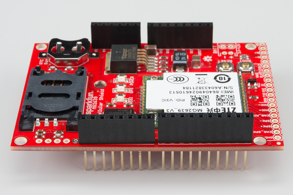
Now that you're familiar with the components and inner workings of the MG2639 Cellular Shield, it's time for some assembly!
Soldering
You'll need to solder a header of some kind to the shield, in order to connect it to your Arduino. Stackable headers are always a popular option as they allow you to plug additional shields or jumper wires into your Arduino's unused pins.
You can also instead use male headers to connect it to the Arduino. If you're looking to use the shield as more of a breakout board, you can solder wires directly to the pins you need.
For more help with shield assembly, check out our Shield Assembly Guide.
Antennae
Both the cellular and GPS functions of the MG2639 require an external antenna connected to the module. There are two U.FL connectors on the side of the chip -- one labled "GSM" the other "GPS."
Any of the quad-band cellular antennas below will work with the shield, but you'll need a U.FL to SMA adapter to complete the connection.
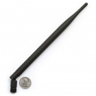
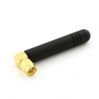
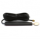
We're working on sourcing a good antenna for the MG2639. We've had success with this patch antenna from Tagolas.
SIM Card
One of the hardest parts in getting the shield to work is finding a suitable network and SIM card to run it on. You may be able to find a sweet, contract-free deal like our T-Mobile 6-month Unlimited card.
Another option is to pick up a prepaid "burner" phone -- like a Go phone -- and swap the SIM card into the shield.
The workings of the SIM card socket can take some getting used to. To unlock the latch, push the top part of the assembly towards the battery, then lift it up. Slide the SIM card into the moving part of the socket with the SIM's notch pointing away from the battery holder.
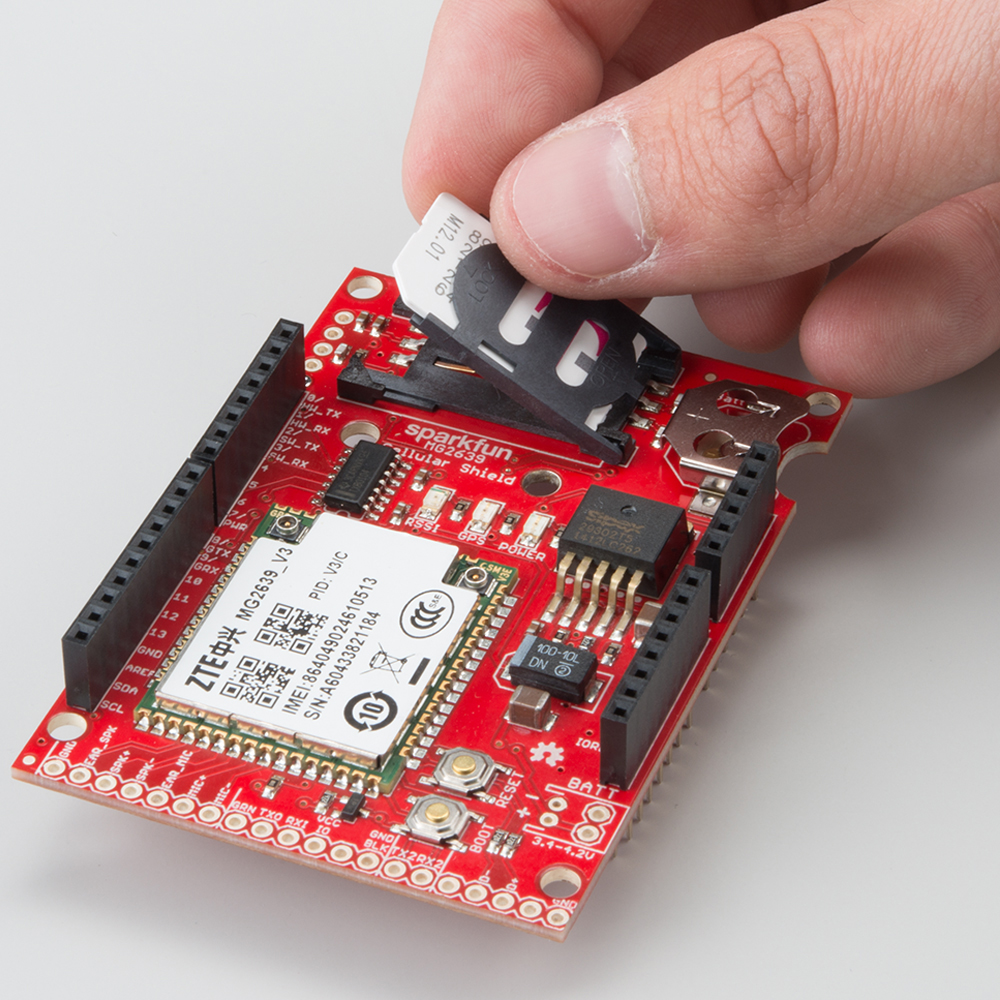
Then fold the arm back into the body of the socket, and gently push it forward towards the "LOCK" position.
Connecting a Speaker and Microphone
To use the MG2639 as a cell phone, you'll need to add some external bits of hardware. The audio port, on the end of the shield, allows you to hook up a speaker and microphone directly to the MG2639's audio interface. The audio port has six pins broken out for speaker, earpiece, and/or microphone hardware. These pins are labeled:
- EAR_SPK -- "Earpiece" speaker. This is a single-ended audio output with 32 Ω impedance. If using this interface, the other pin of the speaker should be connected to ground.
- SPK+ and SPK- -- Differential speaker interface. If using this interface, the two pins of a speaker can be tied directly to these two pins.
- EAR_MIC -- "Earpiece" microphone. This is a single-ended audio input. If you use this interface, connect the other microphone pin to ground.
- MIC+ and MIC- -- Differential microphone input. If you're using this interface the two microphone pins can be connected directly to these pins.
There are a variety of speakers and microphones that can be connected to these pins. If you just want to try a simple proof-of-concept, you can use our Electret Microphone and Thin Speaker to test the interface out.
Section 4.4 of the MG2639 Hardware Development Guide includes some excellent information about connecting an audio interface to the MG2639. Consult that document for more information about the impedances, offset voltages, and sensitivities.