- Home
- Product Categories
- Flex / Force
- SparkFun Load Cell Amplifier - HX711

SparkFun Load Cell Amplifier - HX711
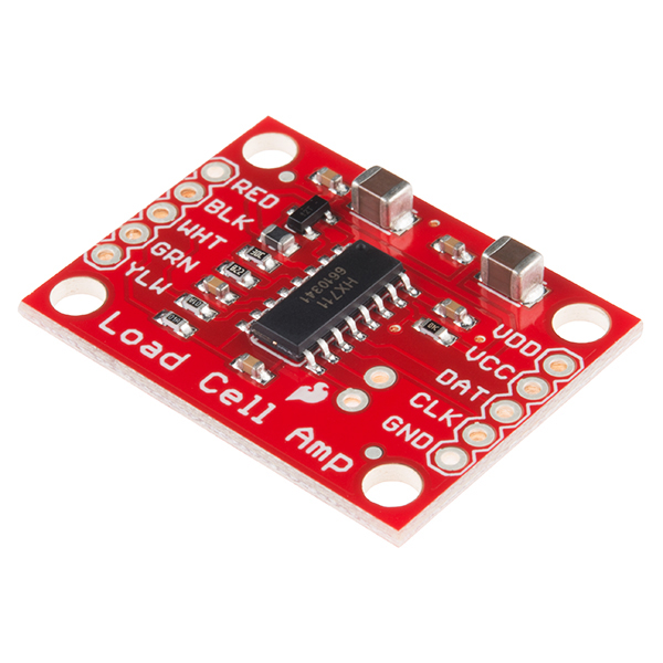
The SparkFun Load Cell Amplifier is a small breakout board for the HX711 IC that allows you to easily read load cells to measure weight. By connecting the amplifier to your microcontroller you will be able to read the changes in the resistance of the load cell, and with some calibration you’ll be able to get very accurate weight measurements. This can be handy for creating your own industrial scale, process control or simple presence detection.
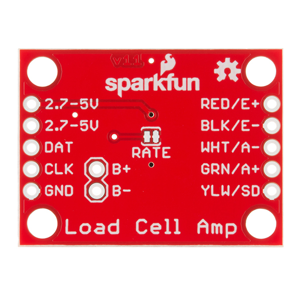
This version of the SparkFun Load Cell Amplifier features a few changes that you specifically asked for! We have separated the analog and digital supply, as well as added a 3.3uH inductor and a 0.1uF filter capacitor for digital supply. Need even more? Checkout the SparkFun Qwiic Scale. It has all the features of the HX711 but with additional library support, a true I2C interface, and no soldering required!
The HX711 uses a two-wire interface (Clock and Data) for communication. Any microcontroller’s GPIO pins should work, and numerous libraries have been written, making it easy to read data from the HX711. Check the hookup guide below for more information.
Load cells use a four-wire Wheatstone bridge configuration to connect to the HX711. These are commonly colored RED, BLK, WHT, GRN and YLW. Each color corresponds to the conventional color coding of load cells:
- Red (Excitation+ or VCC)
- Black (Excitation- or GND)
- White (Amplifier-, Signal- or Output-)
- Green (A+, S+ or O+)
- Yellow (Shield)
The YLW pin acts as an optional input that is not hooked up to the strain gauge but is utilized to ground and shield against outside EMI (electromagnetic interference). Please keep in mind that some load cells might have slight variations in color coding.
Note: Special thanks to Bodge for supplying the Library for the HX711!
- Operation Voltage: 2.7V--5V
- Operation Current: < 1.5mA
- Selectable 10SPS or 80SPS output data rate
- Simultaneous 50 and 60Hz supply rejection
- Schematic
- Eagle Files
- Hookup Guide
- Getting Started with Load Cells
- Datasheet (HX711)
- GitHub (Design Files & Example Code)
- GitHub (Library)
SparkFun Load Cell Amplifier - HX711 Product Help and Resources
IoT Weight Logging Scale
May 9, 2018
This tutorial will show you how to make a scale that logs your weight to a custom website on the Internet. The principles can be extrapolated to any type of data.
Getting Started with Load Cells
June 11, 2015
A tutorial defining what a load cell is and how to use one.
Core Skill: Soldering
This skill defines how difficult the soldering is on a particular product. It might be a couple simple solder joints, or require special reflow tools.
Skill Level: Noob - Some basic soldering is required, but it is limited to a just a few pins, basic through-hole soldering, and couple (if any) polarized components. A basic soldering iron is all you should need.
See all skill levels
Core Skill: Programming
If a board needs code or communicates somehow, you're going to need to know how to program or interface with it. The programming skill is all about communication and code.
Skill Level: Rookie - You will need a better fundamental understand of what code is, and how it works. You will be using beginner-level software and development tools like Arduino. You will be dealing directly with code, but numerous examples and libraries are available. Sensors or shields will communicate with serial or TTL.
See all skill levels
Core Skill: Electrical Prototyping
If it requires power, you need to know how much, what all the pins do, and how to hook it up. You may need to reference datasheets, schematics, and know the ins and outs of electronics.
Skill Level: Competent - You will be required to reference a datasheet or schematic to know how to use a component. Your knowledge of a datasheet will only require basic features like power requirements, pinouts, or communications type. Also, you may need a power supply that?s greater than 12V or more than 1A worth of current.
See all skill levels
Comments
Looking for answers to technical questions?
We welcome your comments and suggestions below. However, if you are looking for solutions to technical questions please see our Technical Assistance page.
Customer Reviews
4.4 out of 5
Based on 43 ratings:
Small and simple.
It gets the job done. The labels are clear and easy to read. The example code had only one minor issue: include <name> vs include "name" and worked just fine after it was resolved. Thanks for a nice web site with all the cool stuff.
worked great!
Followed the hookup guide and it worked perfect with my Arduino Uno! Very easy to use with a load cell.
It works just like any other HX711
I was comparing this to some of the others that I've picked up and really don't see much in a difference for readings other than it is a bit more expensive. Its nice that they at least have dropped the price a little from when I bought it.
I do have to say the Sparkfun library is great as its probably the most comprehensive when setting up a load cell or tieing in 4 load sensors.
It took me a little researching on the differences between a load cell and a load sensor.
You can tie 1 load cell into the hx711 or you can tie 4 load sensors into this using a wheatstone bride.
Perfect for my sugar rocket motor test stand!
I knew Sparkfun was the place to go to get the components I needed for our experimental sugar rocket motor test stand with data logger. Now we can fine tune the Buder Rocket Boy’s sugar rocket engine formula this winter perfecting a replacement for commercial hobby rocket motors. The XH711 along with the 10kg straight bar load cell (TAL220) was a perfect fit. Precise, compact and at a great price. Thanks guys for designing and supplying awesome stuff!
Well done product
Well designed, works as advertised, documentation and SW is freely available. It took just few minutes to power it up and get good reading. I am very satisfied with this product.
Great board
Connection to cell are best done soldered directly to load cell. Awesome amplifier.
Good value and easy to follow guides for beginners like me
Had it up and publishing(Uno and Ethernet shield) to broker in 30 minutes.
0 of 1 found this helpful:
easy to integrate with tutorials
This was my first time using load cells and did not know what to expect. I read the tutorials and got it wired up easily. I got it hooked up to my Arduino and with the library that Sparkfun provides I got it running with no fuss at all. The one problem I had was that the rate that it was updating was not very fast. After some reading I realized it has a jumper on the bottom which if you bridge will increase the data rate. Once I did that it worked perfectly for my application.
Still in the box!
I have not yet been able to work on my scales projects. I will update this review once I've completed the two projects.
Easy to use and accurate
This was surprisingly accurate. My load cell was for 780 g max. I calibrated it for 32 g, (two 1/2-13 nuts) weighted with a scale accurate to .001 g and then tested it up to 320 g. It was spot on.
The one problem I had was in finding the calibration constant. Mine was far different (much larger) than the example given in the tutorial, and the calibration program would have taken forever to slowly find it. I modified the program so it would take bigger steps and zero in on the constant faster.
Really helpful!
This really saved my partner and I for our project and the product got to my home faster than expected.
0 of 7 found this helpful:
4 weeks and I still don't have it.
FedEx sent my package all over the country. 4 weeks later I still don't have it.
Good product, and remarkably tolerant of my stupidity
Very impressed. Through means of some heavy-duty stupidity on my part, I had to de-solder and re-solder some connections between the amps and the rest of my project multiple times. I thought sure I'd used too much heat and had destroyed the traces, but nope: both of my load cell amplifiers are still working flawlessly.
Easy to use amp
This is a great product and it's really easy to install and use. I would definitely use it again.
Works great!
BEWARE! The HX711 is an analog-to-digital converter! It is not a simple amplifier! I went back and reread the product description and it's not really obvious from reading the Sparkfun website. After I figured out how to get the data from the thing, everything went smoothly and the weighing systems appears to be accurate and repeatable.
Works great- see forum for device modifications for teensy
Hey, so as of Oct-2017, the Teensy 3.X core "shiftIn" function that is used by the default HX711 library is too fast. I opened a github issue, pjrc forum post, and sparkfun forum that all link together (as the three threads related to each other.) There's a simple fix involving a delaymicro(1) in the library code
It's up in the air as of october 2017 whether this is a HX711 library issue, or a teensy issue, insofar as teensy core is not emulating the slow AVR functionality, but at the same time, to add the delay to the core could disrupt code that relies on the teensy being faster with ShiftIn than the stock.
Anyway, after documenting my problem and getting community help on the fix, although it was a major hassle at first to use the HX711 breakout, it was an awesome demonstration of the community :). I hope it works well for you!
The actual results I'm getting from the HX711 are great. It's superb to have a 24-bit device so easy to use and relatively cheap :)
Sparkfun should add some clarity on what the excitation voltage is for the HX711 breakout, and not assume everyone will want to calibrate their load cells and/or doesn't have a datasheet for it. I was expected 4.2V from background reading on the HX711, but measured an excitation of 4.36V, and just a little bit of clarity on that core functionality might be useful. Maybe I didn't see it in the guide, but the guide seemed to try and abstract what was going on with its calibration example, and may have been more educational if it got into excitation voltages.
Good Product and Great "Getting Started"
A super simple solution with a typically reliable SparkFun "Getting Started" guide! Using with the Sparkfun Redboard and a single 10kg load cell. The reason i shop with Sparkfun, is that I find their product guides understandable and complete. This is another example of a great guide and, of course, it was written by Nathan. I can quickly get started with the features of the project and world domination...
Used for robot paws!
I have a quadruped under construction, and each foot has a load cell to measure paw pressure to assist with balance calculations. I'm using non-SparkFun micro load cells, electrically similar to those SparkFun sells. I interface each HX711 to a 16-bit PIC and that has worked well. When the HX711 DAT signal goes low, indicating data available, it triggers an interrupt and all the CLK pulsing, and DAT reading, is handled by bit-banging in a loop in the interrupt service routine. It's easy, responsive and low-overhead.
Measure Force
The HX711 amp made the connection simple and easy, and works great!
You can't beat this!
Easy to use, inexpensive, and very reliable. I love these.
Digital CG Scale
I use three HX711 to evaluate the CG of my RC planes. Works so far fine.
Nice load cell interface
I got this recently to go along with the wheatstone bridge combinator board so I could hack a bathroom scale to use as a load cell in a project. The HX711 made the signal from the strain gages readable with an Arduino. It all works pretty good!
Great ADC module
While meant for load cells, this is a great general purpose ADC module. I've used it across projects and embedded platforms for a better ADC than is typically included on chip. I love the serial communication model. Would be 5 stars if it didn't have a maximum pulse width for the serial clock.
yet another sparkfun product that works great
works as expected, great hardware and components, libraries are well implemented yet again another reason why sparkfun staff is the goto for real life projects.
Works great!
He had no issues setting this up with our load cells and it works like a charm!
Good and simple!
Good and simple, easy to use!
Great Load Cell Amplifier
Easy to setup and get working with a load cell. Bonus feature is having the four mounting holes for attachment to your project.
Well designed, easy to use.
This is by far the easiest way I have found to get a load cell into a prototype design, along with the TAL221 micro load cell. The chinese datasheet is not great, but we got descent results with the https://github.com/tatobari/hx711py/ library on a Pi.
It is so simple to use and astonishingly accurate and stable.
Just what I needed
I have a 250 pound scale that came in a surplus lot that didn't have a loadcell amp or readout. I hooked this amp to my loadcell and ardrino, calibrated it and now I have a working scale. The next step is to attach a LCD display to the ardrino and make a portable unit
Perfect for scale applications
Great for retrofitting any modern digital scale into a smart scale!
Simple yet perfect solution
to build a force measuring sensor for any robotic application out of the bathroom scale. Big part of the package is the "how to" documentation on Sparkfun website. Easy to turn every scale from the store into the precision sensor. I've made 3 of those already. Thank you!
I DID NOT RECEIVE IT
The shipping company claimed that it will be received by me in 2-4 days maximum, but forget about 2-4 days it still has not received by me. It has been a month and I cancelled the the shipment. I want to return it.
Please fill out a return ticket and we will get you taken care of: https://www.sparkfun.com/returns
Great board but ... fixed I2C address
SUPER idea to add I2C bus access to the Weight bridge, but if you cannot change the address for the module you cannot add more than 1 Load Cell to the bus. Why not add some facilities to select the I2C hardware address via jumpers or solder-on resistors or so?
Great Load Cell Amp!
This item functioned as expected.
So much fun and works as expected
Successful integration into my product. Works well at a great price. I will put a dig in at Adafruit, I don't but from them after a poor experience. Sparkfun is my supplier of choice. I was a little disappointed that Sparkfun only has support for Arduino and C++, but they make no claims otherwise. Fortunately there is ample support for Pi and python out there in the world.
I can't believe they don't come with headers.
This really irks me, that the breakout doesn't come with headers.
The formula for the output voltage AVDD appears wrong in the HX711 datasheet and the SparkFun schematic. I think it should be VAVDD = VBG*(R1+R2)/R2 ... not R1 in the denominator. My derivation and measurements support this. I had to dig into this to use VSUP = DVDD = 3.3 V and change the 20 KΩ resistor to a 10 KΩ for a different load cell excitation voltage.
In order to get the 80Hz as promised from the data sheet sparkfun documentation says to open the jumper. How can I do that? If I understand correctly right now the pull-up resistor is now low. What can I do to flip it to high?
If you read the HX711 data sheet, you'll see that it specs a range of 2.7 V to 5.5 V for DVDD and VSUP. So there is no reason why you can't use single 3.3 V supply for both VCC and VDD with this board.
HOWEVER -- read that data sheet again. There is a statement: "When using internal analog supply regulator, the dropout voltage of the regulator depends on the external transistor used. The output voltage is equal to VAVDD=VBG*(R1+R2)/ R1 (Fig. 1). This voltage should be designed with a minimum of 100mV below VSUP voltage."
(Also, as commenter Member #461211 points out below, the data sheet is wrong -- the denominator should be R2, not R1, and the SparkFun schematic reflects that.)
100 mV is the dropout spec for the HX711's regulator.
So do the math, and AVDD with the resistor values on the board is 4.3 V. With a 5 V VCC, the drop-out spec is easily met. But, obviously with a 3.3 V VCC, there's no way this will work, so you need to adjust the feedback resistors on the board to something that is acceptable. Change R1 from 20k to 11.5k and AVDD becomes 3.0 V, which is obviously 300 mV below the input 3.3 V and it also meets the dropout spec, and the HX711 should work just fine and give you reasonable conversion results.
I thought I couldn't make it switch from channel A to B or vice versa, but I was doing it wrong. It does seem as if any cycle in which you change the channel will be extended to about a 60msec length. So if you alternate between channels, you get about 8 readings per second for each channel. Do other people agree that this is what to expect, or is there some procedure that could speed it up?
There is rather obvious blunder in the schematics. The VDD input is connected to chip DVDD pin as expected. But the R5 pullup on RATE pin is connected to VCC, while it should be in the same digital domain, i.e. also connected to VDD. The filter resistors and a capacitor on B channel would not hurt either.
The resistor on the
RATEpin is a pull-up resistor, which is there for the jumper. Without the resistor, the power would be shorted to ground. Otherwise, if you are referencing the difference between VDD and VCC... that is noted in the schematic and it is also documented in the hookup guide:The rest of the design is based on the reference design in the datasheet.
If you need further technical assistance, please use the link in the banner above, to get started with posting a topic in our forums. Our technical support team will do their best to assist you.
"without the resistor the power will be shorted to the ground" ... what on earth are you talking about?! without the resistor the RATE pin will be either connected to ground (if jumper is on) or floating (if jumper is off). No "power" will be "shorted" in either case.
You totally missed the point. The RATE pin in datasheet is clearly marked as "digital input". Guess what is level "1" when VDD (digital supply) is 3.3V? And what voltage you will be sending to it through pull-up if VCC is 5V?
The point is - any digital pins must remain in digital domain, which means signals on them should not exceed VDD. VCC is analog supply and it should not be used as a source for any pull-ups.
Hmm... this was a while ago, but I remember the question originally being worded as, "why is there a resistor connected to VCC on the
RATEpin?" That is why I presented separate solutions for the possible scenarios:RATEpin would be permanently tied (aka shorted) to ground.Thanks for the prompt reply. Now that we are on a same page, I should say that I am not 100% sure that the rework IS necessary. The datasheet unfortunately does not specify voltage tolerances and I based my comment entirely on common limits for CMOS inputs being around VDD +/- 0.4V.
Our company used these boards before and just to be on a safe side I modded them by cutting trace from R5 to VCC and adding small wire to VDD available on C4 nearby. The PCB rework should be trivial.
Having said that, we recently decided to switch to custom boards because of missing filter on B channel. If you do decide to rework the PCB, I am sure inclusion of a second filter or at least footprints for it would be appreciated by your customers.
I filed another GitHub issue; however, if you have more feature request feel free to file them to the GitHub repository directly.
hi I recently bought the Load cell combinator and load cell amp. When i plug it into an adruino, i can seem to get my readings off 0kg. Will ths be due to faulty soldering, and or maybe soldering the wrong wires onto + - and C?
Where can I buy the HX711 A/D chip only? Thank you!
Review: The HX711 is THE “Mighty Might”! We can’t say enough about this little wonder. The only problem we found was with the omission of one little important item in the documentation and that has to do with increasing the data output rate (at the expense of sample rate/accuracy which we have proven is negligible). The board as supplied has an existing trace between the two solder pads immediately above TRACE and this trace needs to be cut to enable 80 SPS (RBB01). This was required to log the very fast data coming from our Sugar Rocket Motor Data Logger Test Bench. We are capturing a reading every 50 milliseconds and using SparkFun's 10Kg load cell With this we are able to replicate the published data of store bought rocket motors; completely validating what the HX711 can do! The next project I used this on was to measure to a ridicules .01 gram accuracy (utilizing a 300g load cell pulled from a 20$ scale) and also control a stepper motor (stepper motor stops when target weight is reached), all with amazing consistency too! There is absolutely no difference between what you can measure with an HX711 and an expensive digital weigh scale. The BIG difference is that the MIGHTY HX711 can do a lot more & it’s inexpensive too! Buder Rocket Boys (mastering the art of sugar rockets)
Works well for me with a Raspberry Pi. I wrote some threaded C++ code to read weights repeatedly into an array. I also wrote a Python wrapper so you can do that from a Python/C module. Just got around to putting code on GitHub.
https://github.com/jamieboyd/GPIO_Thread
We used it to log data for mice
https://github.com/jamieboyd/AutoMouseWeight
I have a load cell that requires 5 to 10V of power supply. Can I still use HX711? What if I push the power supply to 6V? Will it burn the board?
Very late answer, but might be helpful to next person with same question. 6V is outside of the operating range of the HX711 chip and even if it does not burn right away this is certainly not recommended. You can increase VCC voltage to 5.5V though.
Is there a way to use this with 6 load sensors? I've seen the load sell combinator board, but obviously, that only works if you have 4 load sensors, right? Is there a way to do this with 6?
Getting the following compile error from Arduino IDE. Library used id from https://github.com/bogde/HX711
In file included from Loadcell_Sparkfun_code.ino:34: C:\Users\Jeremy\Documents\Arduino\libraries\HX711/HX711.h:16: error: ISO C++ forbids initialization of member 'OFFSET' C:\Users\Jeremy\Documents\Arduino\libraries\HX711/HX711.h:16: error: making 'OFFSET' static C:\Users\Jeremy\Documents\Arduino\libraries\HX711/HX711.h:16: error: ISO C++ forbids in-class initialization of non-const static member 'OFFSET' C:\Users\Jeremy\Documents\Arduino\libraries\HX711/HX711.h:17: error: ISO C++ forbids initialization of member 'SCALE' C:\Users\Jeremy\Documents\Arduino\libraries\HX711/HX711.h:17: error: making 'SCALE' static C:\Users\Jeremy\Documents\Arduino\libraries\HX711/HX711.h:17: error: ISO C++ forbids in-class initialization of non-const static member 'SCALE'
Anyone encounter this?
What Arduino version and board definition are you using? I was able to install and use that library on 1.6.11 without issue.
Updated to 1.7.11 and compiles fine, but now my arduino isn't recognized by the IDE. Arduino Uno shows up in my "Other Devices" under Device Manager, but I can't install the driver!
Windows gives me this when I point it to the driver folder and try to install:
"windows found driver software but encountered an error while attempting to install it. One of the installers for this device cannot perform the installation at this time"
Never seen this before in my life, been searching relentlessly online for solutions.
To second RobotRacer's comment, I too would be interested to know where I can find the bare IC so I can use it on my own PCB. I'd buy one from SparkFun if they sold it on its own.
Will this work with a pressure sensor where all 4 legs of the wheatstone are variable?
Do you mean the Load Sensors? The load sensors can be configured in a wheatstone bridge, and there's a board for that!
Every load cell I try on this thing drifts waaay more than it's rated - as much as 2% of FS. It seems to drift most with slight temperature changes (10 to 20 deg F). Anyone else having this problem?
Any idea what the maximum output impedance of the sensor can be? Those 100 Ohm resistors makes me think it has to be pretty small.
I have a pressure sensor that's basically a load cell but the output impedance is 1.5K.
1.5k should be fine. The load cells I've used are a little under 2k. The 100 ohm resistors, in conjunction with the 0.1uF capacitor help to reduce noise on the input.
Has anyone had any luck finding the HX711 bare IC available anywhere? We are looking to integrate one into a new PCB, up to now we have been using the first version of this board (works great!!!!!!!) for prototyping. We are just ready to make the next step with development and can't find this chip on SparkFun, DigiKey, Mouser or Arrow. We bought a bunch of these boards and stripped them just to populate some of our boards
We love using spark fun breakouts for prototyping!
AliExpress has some suppliers (I found one with this title: "50PCS HX711 HX711 SOP16") for only a few bucks.
Can I use Three or more HX711 modules each with separate loadcell with a single arduino UNO or mega at a time and make some algebraic sums to find out the total force acting the load cells