SparkFun Load Cell Amplifier - HX711

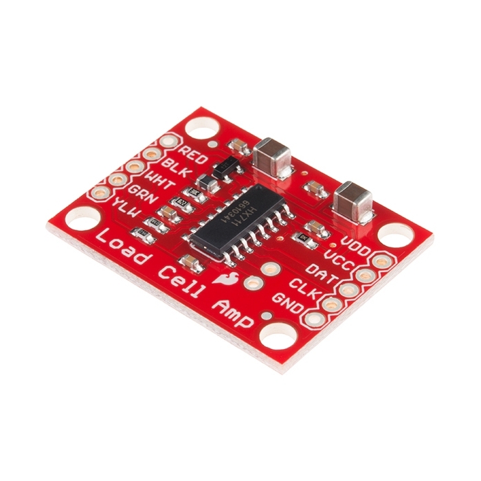
The SparkFun Load Cell Amplifier is a small breakout board for the HX711 IC that allows you to easily read load cells to measure weight. By connecting the amplifier to your microcontroller you will be able to read the changes in the resistance of the load cell and with some calibration you’ll be able to get very accurate weight measurements. This can be handy for creating your own industrial scale, process control, or simple presence detection.

The HX711 uses a two wire interface (Clock and Data) for communication. Any microcontroller’s GPIO pins should work and numerous libraries have been written making it easy to read data from the HX711. Check the hookup guide below for more information.
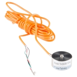
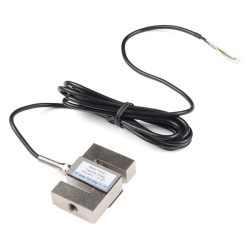
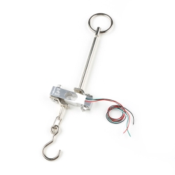
Load cells use a four wire wheatstone bridge to connect to the HX711. These are commonly colored RED, BLK, WHT, GRN, and YLW. Each color corresponds to the conventional color coding of load cells:

  • Red (Excitation+ or VCC)
  • Black (Excitation- or GND)
  • White (Amplifier+, Signal+, or Output+)
  • Green (A-, S-, or O-)
  • Yellow (Shield)

The YLW pin acts as an optional input that is not hooked up to the strain gauge but is utilized to ground and shield against outside EMI (electromagnetic interference). Please keep in mind that some load cells might have slight variations in color coding.

Note: Special thanks to Bodge for supplying the Library for the HX711!

  • Operation Voltage: 2.7V-5V
  • Operation Current: < 1.5mA
  • Selectable 10SPS or 80SPS output data rate
  • Simultaneous 50 and 60Hz supply rejection

SparkFun Load Cell Amplifier - HX711 Product Help and Resources

OpenScale Applications and Hookup Guide

July 22, 2016

OpenScale allows you to have a permanent scale for industrial and biological applications. Learn how to use the OpenScale board to read and configure load cells.

Getting Started with Load Cells

June 11, 2015

A tutorial defining what a load cell is and how to use one.

Load Cell Amplifier HX711 Breakout Hookup Guide

July 22, 2016

A hookup guide for the HX711 load cell amplifier breakout board

Core Skill: Soldering

This skill defines how difficult the soldering is on a particular product. It might be a couple simple solder joints, or require special reflow tools.

1 Soldering

Skill Level: Noob - Some basic soldering is required, but it is limited to a just a few pins, basic through-hole soldering, and couple (if any) polarized components. A basic soldering iron is all you should need.
See all skill levels


Core Skill: Programming

If a board needs code or communicates somehow, you're going to need to know how to program or interface with it. The programming skill is all about communication and code.

2 Programming

Skill Level: Rookie - You will need a better fundamental understand of what code is, and how it works. You will be using beginner-level software and development tools like Arduino. You will be dealing directly with code, but numerous examples and libraries are available. Sensors or shields will communicate with serial or TTL.
See all skill levels


Core Skill: Electrical Prototyping

If it requires power, you need to know how much, what all the pins do, and how to hook it up. You may need to reference datasheets, schematics, and know the ins and outs of electronics.

3 Electrical Prototyping

Skill Level: Competent - You will be required to reference a datasheet or schematic to know how to use a component. Your knowledge of a datasheet will only require basic features like power requirements, pinouts, or communications type. Also, you may need a power supply that?s greater than 12V or more than 1A worth of current.
See all skill levels


Comments

Looking for answers to technical questions?

We welcome your comments and suggestions below. However, if you are looking for solutions to technical questions please see our Technical Assistance page.

  • Member #480979 / about 8 years ago / 3

    One thing to note, not that it is specifically mentioned, but this chip is not I2C. Although the pins are labeled DAT and CLK and it is 4 pins, this is NOT I2C.

  • Member #735218 / about 9 years ago / 2

    Is there any schedule/planning, when this item will be back on stock?

  • Brad10 / about 8 years ago / 1

    What's the story on availability of this part? I've just finished a Dog Bed Scale using this part, and started on a Dog Water Bowl Scale using the same part - lucky me I ordered an extra. Is it obsoleted? Will you be replacing it? It'd break my heart to find my two Open Source designs use an unavailable part. I see several customers had trouble getting it wired up, but I think that issue could be overcome as more people publish their projects that use it.

    A Wheatstone bridge amplifier is a basic piece of sensor technology - please make it available again.

    • M-Short / about 8 years ago / 1

      Check back really soon. This is undergoing a small revision and should be available soon.

  • Member #206873 / about 8 years ago / 1

    Hi there, I have a question about the input signal supplied to the HX711. The datasheet states: "Channel A can be programmed with a gain of 128 or 64, corresponding to a full-scale differential input voltage of ±20mV or ±40mV respectively, when a 5V supply is connected to AVDD analog power supply pin." If the input voltage range is +/-20mV, are values outside this range coerced/saturated to the limits? ie what happens if a signal of +/-30mV is applied when the gain is set so the input limit is +/-20mV? thanks, Matt

  • Member #806655 / about 8 years ago / 1

    I'm new to load cells, but I'm looking to read from an industrial load cell that specifies an excitation voltage of 10 Vdc. I would assume that connection this HX711 to an Arduino Zero at 3.3V would still work. Would I lose precision or get more noise? I'm weighing a human (100-350 lbs) in a chair, and a reading within +/- 5 lbs would be awesome, and +/- 10 lbs would be acceptable.

  • jgeating / about 8 years ago / 1

    Any way this could be used with just one of the single strain gauge load sensors (https://www.sparkfun.com/products/10245)? I’d like to put two sets of four of these in a rectangle and independently measure the forces to detect weight shifts. Getting the $56 full bridge load cells gets real expensive at qty. 8 though. Perhaps completing the bridge somehow with static resistors. Or do these need to be real fancy precision resistors?

  • Megaman / about 8 years ago / 1

    I'm planning on using this with the straight bar load cell (TAL220), but I need a resolution of around 10mg. The load cell states that it outputs 1mV/V, so with 5V excitation I would get 5mV with a load of 10Kg.

    Now, I am getting confused with the gain on this amplifier, with a gain of 128 the input would be 0.64V at full load, but what is the reference voltage? Or am I not thinking about this properly?

    • The HX711 has a 24-bit ADC so you'll see a 1-bit change for every (5v / 2^24) = 0.0000000596V. In reality there's noise that has to be averaged out.

      From my comment below: I was able to get 0.25kg (0.5lbs) accuracy with the 200kg load cell which is about what the datasheet spec is (Combined error 0.05%). I would suspect you could obtain deltas in readings in the 0.01kg or 10g range from your 10kg load cell. You're looking for 10mg (3 orders of magnitude better ) - I'm not sure what that would take but temperature variance, electrical noise, even gusts of air would become problematic.

      • Megaman / about 8 years ago / 1

        Thanks Nate, I actually mis-typed in my previous comment, I meant that we needed resolution of around 10g...

        I got it working, and I am getting readings with precision in the 0.0001kg range(0.1g), so it works for my purposes. If it is usefull to anyone I got the reference voltage for the calculations from the Full Scale Differential input range value in the datasheet and used that as the max voltage (2^24 for data).

        It's fun when you don't have to use the provided library (as useful as they are)

  • aloo / about 9 years ago * / 1

    Has anyone successfully used either bogde's library or agueuo's library on an Arduino DUE? I am able to get the Sparkfun firmware examples to run on a MEGA. For the DUE it will compile, but my serial monitor ends up just being blank.

    I imagine that it has something to do with differences in architecture between AVR and ARM, but I am not familiar enough with either to know where to go from there.

    Any thoughts would be greatly appreciated.

    • aloo / about 8 years ago * / 1

      After some poking around, I found the issue. The Due does not seem to process data type char the same way as AVR based boards do. I switched the two instances of char (found on lines 46 and 47 of HW711.cpp) to int8_t. It should now read as follows:

      for (int8_t j = 3; j--;) {
        for (int8_t i = 8; i--;) {
      

  • Member #376156 / about 8 years ago / 0

    Dear SparkFun,

    When will this product be in stock again?

    Best regards.

    • Very soon! Keep an eye on the new product feed - we have a revision coming out in the next couple of weeks.

  • andrewstapleton / about 9 years ago / 2

    Does anyone know if this unit automatically resets (zero) on 'boot' or will it simply measure the current weight from the load cell after a restart/startup allowing for manual callibration via a microcontroller?

    • Check out the example sketches. Upon power up the HX711 will report the 24-bit ADC value, something like 8,490,772. What you normally do is create a system where you find your tare value (for example 8,480,021) and a calibration value (each change of 10,320 is a pound). Now when you turn on your system and take a reading, you'll know how much weight is sitting on your scale (I read 8,490,772 which means I'm 10,751 more than my zero, which is slightly more than a pound on my scale). Sounds complicated but the example sketches demonstrate how to do all this.

      • andrewstapleton / about 9 years ago / 2

        Works brilliantly Nate ! The library and example sketches are excellent. :)

  • henryhbk / about 9 years ago / 2

    Can you comment on the sensitivities on each of the load cells? (e.g. the 10Kg one can detect the difference of X grams, etc)?

    • I was able to get 0.25kg (0.5lbs) accuracy with the 200kg load cell which is about what the datasheet spec is (Combined error 0.05%). The HX711 has much higher precision than that (24-bit) but the calibration and averaging reduces it down.

  • Member #482343 / about 9 years ago / 1

    I cannot find the information about the physical dimensions. I.e. the overall dimensions, and especially the location and size of the mounting holes. I realize there is a picture of the board with rulers next to it, but that is not sufficient to actually draw the appropriate locations of the mounting holes.

    The data sheets all seem to be about the electrical characteristics, and omit the dimensional data.

  • What is the proper syntax for saving the scale output in a variable?

    float value;

    Serial.print(scale.getGram(), 1); <----- WORKS

    value = (scale.getGram(), 1) ;

    Serial.println(value); <----- NO GOOD! DISPLAYS: "1.00"

    value = (scale.getGram(), 2) ;

    Serial.println(value); <----- NO GOOD! DISPLAYS: "2.00"

    • ShapeShifter / about 9 years ago / 1

      You've probably figured it out by now, but just in case, try this:

      value = scale.getGram();
      Serial.println(value, 1);
      

      The ", 1" part is an extra parameter for the Serial.println() function call, which tells it how many decimal places to print when printing floating point numbers. It has nothing to do with the scale.getGram() call.

  • Member #717487 / about 9 years ago / 1

    Can anyone tell me if this will work without issue on a 3v3 microcontroller, such as the Particle (formerly Spark) Core?

  • furnissj / about 9 years ago / 1

    The wire colors in the product description are inconsistent with the schematic and the load cells sold on the site. I believe the correct wire color scheme is as follows: (RED) + Excitation (BLACK) - Excitation (GREEN) + Signal (WHITE) - Signal

  • Member #699605 / about 9 years ago / 1

    Can this and the 50kg load cell be measured just using a multimeter and not worrying about an Arudino?

    • Unfortunately no, you need a microcontroller (or Bus Pirate) of some sort. The HX711 has a digital interface so you'll need something to twiddle the pins to get the digital data out of it.

  • Member #694983 / about 9 years ago / 1

    What is the bias current of the HX711? This is necessary to decide the maximum resistance of an appropriate Wheatstone bridge.

    • We use the MMBT4403 PNP transistor as part of the onboard voltage regulator. This can source up to 600mA meaning the minimum resistance of your bridge could be quite low (8.3Ohm or greater). In practical use I would say the minimum Wheatstone bridge resistance would be in the hundreds of Ohms.

  • Member #399878 / about 9 years ago / 1

    Would this work well with the eTape liquid level sensor?

    • The HX711 is made specifically for wheatstone bridges and very small changes in resistance (fractions of an Ohm). The eTape sensor has a much larger change in resistance (350 to 1500 Ohm) so no, this wouldn't work with the eTape sensor. However, you should be able to hook the eTape sensor directly to nearly any microcontroller that has an onboard ADC.

    • Sure it would work; it should be interesting to see if you get better performance than a simple voltage divider and a 10 bit A/D. The eTape Wheatstone bridge configuration will give a full scale signal that's practically linear, which is very convenient. Referring to the eTape datasheet, try using 75K for R1,R2 and 900 Ohms for Rref to get a +/-40mV signal for the HX711.

  • Member #401531 / about 9 years ago / 1

    I was just wondering what the usable range is on this board? As in could i use it for loadcells rated at 80000kg? And what sort of accuracy would i get with that?

    • The rated load of a load cell is not important. As long as the load cell is setup in a wheatstone bridge configuration, has a rated output of mV/V, and has an excitation voltage of 5V-12V, it should work.

      I can't say it will work with every load cell but the HX711 breakout board works with every load cell I have ever met.

  • Member #457669 / about 9 years ago / 1

    how often/fast can I pole a strain gage with this board? Trying to look at peak strain in a cylinder that gets a shock type of loading. ...and if you answer, please keep it in simpleton type answers. I am new to all this fascinating stuff. Thanks, Chris

    • The HX711 is not designed to be ultra-fast (it's also not designed for read a strain gauge, it's designed to read four in a wheatstone bridge configuration). This is because it's got an easy to use digital interface that involves taking a reading then serially clocking out of the data. The default rate is 10Hz and this is changeable to 80Hz (please see schematic) but the noise in the readings increases from 50nV to 90nV rms (datasheet page 3). If you need to hammer a strain gauge with readings you might look at an instrumentation amplifier that you can read in the kHz range.

  • RobotRacer / about 9 years ago / 1

    I have been seeing these modules online a lot (putting together a load cell project) but I cannot find the IC used by itself - definitely buying one or more of these, but for future application want to integrate into an IC, any hints?

    • AVIA (the company that makes the HX711) is pretty easy to deal with. So if you need many, check with them. Would you want us to sell the bare IC by itself?

      • RobotRacer / about 9 years ago / 1

        Selling the bare IC would be excellent! Working in an R&D department, your breakouts and kits are great asset for quick and simple development testing, but our end goal is always to integrate into a common board, and an issue we have had with other companies is the availability of the IC's outside of large scale agreements.

        PS. Thanks SparkFun for always being awesome! Loyal customer and always referring SparkFun to everyone

        • Flattery will get you everywhere! Thanks for the kind words. I'll see if we can get the bare IC posted.

  • Qtronik / about 9 years ago / 1

    I wonder if we can compare 4 load cell in each corner of a large plateform? is it feasible with arduino and is somebody had ever make it ? because I think to make an cats weight follower with their litter box with their duty follower too! cool !

  • NorthStreetLabs / about 9 years ago / 1

    is that a silk screen error on the 3D part? on the back of the board, "B+"

    • Nope. B+ and B- are extra, broken out pins for the channel B amplifier on the IC. It's not often used but we decided to break it out in case people needed it. However, the 3D models pull in some extra Eagle layer info so the label JP2 is being overlayed onto the B+/- labels when in reality it's not. I'll see if we can get those layers turned off on our models.

      • PeterP / about 9 years ago / 1

        For folks thinking about attaching a second load cell here's some datasheet info on channel B. It is not quite as sensitive as channel A.

        Channel A differential input is designed to interface directly with a bridge sensor’s differential output. It can be programmed with a gain of 128 or 64. The large gains are needed to accommodate the small output signal from the sensor. When 5V supply is used at the AVDD pin, these gains correspond to a full-scale differential input voltage of ±20mV or ±40mV respectively.

        Channel B differential input has a fixed gain of 32. The full-scale input voltage range is ±80mV, when 5V supply is used at the AVDD pin.

  • Member #499880 / about 9 years ago / 1

    The GitHub link is broken (404).

Customer Reviews

4.1 out of 5

Based on 17 ratings:

Currently viewing all customer reviews.

2 of 2 found this helpful:

Mixed colour messages

Tried connecting according to hook-up guide. Followed colour suggestions too literally. Smoked out the transistor. Turns out the WHT/GRN leads are opposite on the TSA606 (which differs from the picture and other descriptions in comments). I'm not sure how this would have smoked the transistor. Both amp and cell were connected so I can't rule out defective board. I would recommend using E+, E-, S+ and S- instead of colour labels on the PCB, since I have read many reviews about confusion of load cell wire colours. Project is on hold until I get a replacement.

1 of 1 found this helpful:

Works great

I do wish you had separated the analog and digital power rails. Right now it works great on 5v but its tricky to use a 3.3v micro because the clock and data pins are at dvcc.

I made it work by unsoldering the dvcc pin and putting 3.3v on it, the put 5v on the VCC solder tab which is now avcc.

1 of 1 found this helpful:

Packaged DC amp for load cells.

Plugged (correct) leads from load cell to board, connected to Pro mini, loaded test program and success. Biggest problem was the 200kg load cells lead colors did not match spec sheet. Smoked first board trying to find why it didn't work. Did a 4x4 resistance matrix on the load cell and it was obvious what were the correct connections. Put correct leads into the replacement board and it worked perfectly. A needed product.

Works great

Easy to use and well worth the small cost, way to go SparkFun!

Super simple, plug and play!

The tutorial made it really simple to get readings from a bathroom scale load cell.

The HX711 system

The Amplifier board is a plus..it works. It collects the four load cell analog signals, detects the bridge change, performs a A/D and outputs the digital signal to the Arduino. however, you need to explain that there are 2 strain gages at each cell. Use a proper schematic and label inputs as Vcc, Gnd, O+ and O- on the 711 board. Then label the software zero setting that must be tweaked as well as the gain setting. Also Github doesn't work to insert the library and software. A plus is the system works at 3.5V. Also, the 711 board could have a female connector so that an option is purchasing a 5-ft length of shielded cable to hook to the Arduino. (hardly anyone would put the arduino on the floor with the scale)... I hope this helps to resolve problems by others (the guy who fried a board)...

Easy to setup, clear instructions and tutorial. Works inmediatelly and very well.

Haven't used it yet

I am designing a scale that uses two load cells so I need two channels. i bought this board along with the combinator board. However, the combinator board only allows connection of load cells with three conductors whereas my load cells have four. So, I had to buy a different board that is designed to handle two channels (E+, E-, A+, A-, B+ and B-) Thanks

Good product according to specifications.

Long delivery time to Europe.

What a good bathroom scale to hack?

I want to hack a bathroom scale and there are several for @$14 on Amazon. Anyone know of one that has for certain has the BWR 3 wire sensors that the SparkFun Load Sensor Combinator board is looking for?

One of the best things I have owned

I built a scale for counting lams in a motor (at a motor co.) I am systems eng at a major motor mfg co. We now are able to count lams and even small parts with the scales. Works great and things just fell into place. I like that. You did well ( or even great) with this part. I did have to go to a larger load cell.

Thanks again.

W Robinson

Powered up and worked the first time, with load sensors and combinator

I built a dog weight scale using this board, 4 Load Sensors, a Load Sensor Combinator board, and an Arduino. To my surprise it worked the first time I turned it on. After a little calibration it gave usable results. I'm impressed by the lack of noise and how easy it was to interface to this board via the HX711 library.

works good

easy to use although the pcb is large

A Little More Info May Help- Now 5 stars

Troubleshooting info would be nice and info on how to best mount the load sensors as well. Thus far I haven't gotten a usable reading but to be fair, I haven't been able to find a good calibration value nor have I double checked my soldering as closely as I will likely need to. In terms of finding a good calibration though, I took a stab at adding some automation to the already well used calibration arduino script. You can find it here: https://github.com/thecircleh/eir/blob/master/Calibratescale.ino 5 stars for the product if I can get good readings. UPDATE : 7/9/16. Well I got it to finally work. For my test I simply taped the load sensors into place. Equally spaced in an array of 4. Powered with 3.7 volts. Used a heavier calibration weight (my son) and the above reference script. Voila!!!!

Awesome

Superb.....

SparkFun Load Cell Amplifier - HX711

Simple to use and works very well.

Worked as intended

Really, you grab the library and you are good to go. Seems to work with all of the normal pins, analog, digital, and interrupt.