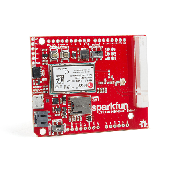
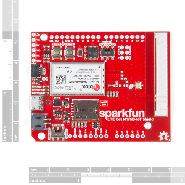
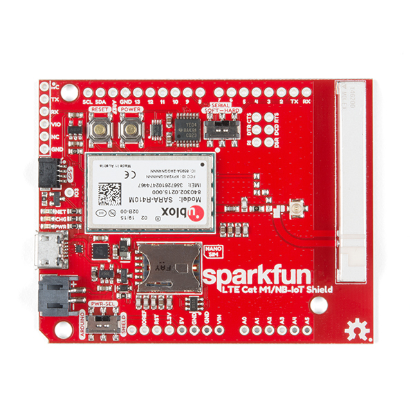
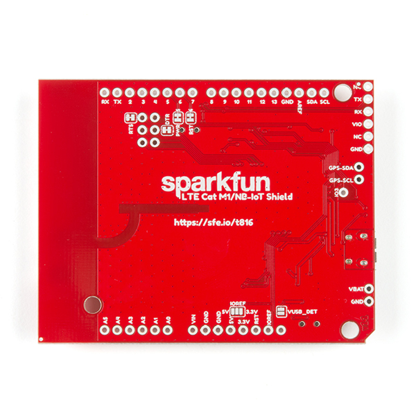
The SparkFun LTE CAT M1/NB-IoT Shield equips your Arduino or Arduino-compatible microcontroller with access to data networks across the globe. This shield adds wireless, high-bandwidth cellular functionality to your IoT project while maintaining low power consumption and a small footprint. The SparkFun LTE CAT M1/NB-IoT Shield is based off the Arduino R3’s footprint that allows you to easily incorporate it with favorite Arduino-based device.
At the heart of the LTE Cat M1/NB-IoT shield is a u-blox SARA-R410M-02B LTE Cat M1/NB-IoT modem. Cat M1 (Category M1) and NB-IoT (Narrowband IoT) are both Low Power Wide Area Network (LPWAN) technologies that are designed to provide cellular communication to small IoT devices. They operate on LTE network bands just like most smartphones, and should be supported by most cellular network carriers. The u-blox SARA-R4 module communicates over a UART via a simple AT command set. We’ve provided a library to help you get started with everything from sending SMS text messages to communicating with servers over a TCP/IP connection. Additionally, both the module and library support an I2C GPS interface via a Qwiic connector, so you can plug in a u-blox GPS module and start remotely tracking your project.
Each SparkFun LTE CAT M1/NB-IoT Shield also includes a ceramic, Molex 1462000001 SMD antenna. The antenna has a gain of 3.8dBi around 1.7GHz to 2.7GHz. However, if you would prefer to use an external antenna, we have provided a U.FL connector that can be utilized by simply slicing through a jumper with a hobby knife.
Please be aware that there are a few extra parts required to get this shield fully functioning, other than an Arduino-based device. First, you'll need to supply your own SIM card, such as this one from Hologram (we do also offer this shield with an included one as well) and your own headers which will need to be soldered on.
Note: Be sure to check the Hardware Overview section in the Hookup Guide for compatible GPS modules. The onboard Qwiic connector is only designed to support u-blox-based GPS modules. It does not support any other GPS modules or sensors. We are continuing to add more modules so be sure to check back every so often to find out more!
SparkFun LTE CAT M1/NB-IoT Shield - SARA-R4 Product Help and Resources
LTE Cat M1/NB-IoT Shield Hookup Guide
November 20, 2018
The SparkFun LTE CAT M1/NB-IoT Shield equips your Arduino or Arduino-compatible microcontroller with access to data networks across the globe. This shield adds wireless, high-bandwidth cellular functionality to your IoT project!
Three Quick Tips About Using U.FL
December 28, 2018
Quick tips regarding how to connect, protect, and disconnect U.FL connectors.
Hologram eUICC SIM Special Features Compatibility with SparkFun LTE CAT M1/NB-IoT Shield - SARA-R4
The Hologram enhanced eUICC SIM card [ e.g. CEL-17117 ] will work with SparkFun LTE CAT M1/NB-IoT Shield - SARA-R4 [ e.g. CEL-14997 ] but the special eUICC features will not be operable with the shield at this current time.
If you need further assistance with these key features please visit the Hologram support forum:
Core Skill: Soldering
This skill defines how difficult the soldering is on a particular product. It might be a couple simple solder joints, or require special reflow tools.
Skill Level: Noob - Some basic soldering is required, but it is limited to a just a few pins, basic through-hole soldering, and couple (if any) polarized components. A basic soldering iron is all you should need.
See all skill levels
Core Skill: Programming
If a board needs code or communicates somehow, you're going to need to know how to program or interface with it. The programming skill is all about communication and code.
Skill Level: Rookie - You will need a better fundamental understand of what code is, and how it works. You will be using beginner-level software and development tools like Arduino. You will be dealing directly with code, but numerous examples and libraries are available. Sensors or shields will communicate with serial or TTL.
See all skill levels
Core Skill: Electrical Prototyping
If it requires power, you need to know how much, what all the pins do, and how to hook it up. You may need to reference datasheets, schematics, and know the ins and outs of electronics.
Skill Level: Competent - You will be required to reference a datasheet or schematic to know how to use a component. Your knowledge of a datasheet will only require basic features like power requirements, pinouts, or communications type. Also, you may need a power supply that?s greater than 12V or more than 1A worth of current.
See all skill levels
Comments
Looking for answers to technical questions?
We welcome your comments and suggestions below. However, if you are looking for solutions to technical questions please see our Technical Assistance page.
Customer Reviews
3.1 out of 5
Based on 7 ratings:
2 of 2 found this helpful:
Does not work on Verizon and no one seems to care.
https://forum.sparkfun.com/viewtopic.php?f=115&t=52262&p=212631&hilit=verizon#p212631
No response in over a year. Not sure if anyone else has this issue but I have spoken with Verizon on their IOT support and the manufacturer has to register with the network. Ublox has, but it seems like Sparkfun hasn't done their part. Maybe a 1 star review will get some attention. Since I don't know how to give it a 0 star review because it only sort of works as far as registering on a network other than Verizon but seems to fail to communicate further.
4 of 4 found this helpful:
Works nicely. Plug and play
I own 5 of these. Communication works great but there are missing pullup resistors on both sides of the logic converter that causes communication issues when extending wires to the module. Using it with an arduino uno causes no issues. I believe the esd diode for the sim card might not be connected properly since most of my modules are dead from electrostatic shock. Note TX and RX are flipped on the UART module. The datasheet briefly mentions that TX pin from the sara module receives and the RX pin sends data
1 of 1 found this helpful:
Unable to send SMS to Verizon cell phone.
Purchased a Hologram SIM and established an account. Using the shield's Example 01 I tried sending an SMS to my verizon cell phone. The shield reports ok and Hologram reports data used. But, the message never arrives. The forum topic on this issue seems to indicate SparkFun has no clue about this matter and is not engaged in finding a reason. From what I see also in the forum, Hologram also is not engaged. Am going to attempt to engage with Hologram but am not going to hold up my project much longer. There are alternatives.
1 of 1 found this helpful:
Arduino/Hologram examples need updating
The examples no longer match the Hologram IoT dashboard. I was able to get the 00_Register_Operator and 01_SMS_Send to work but after that the examples don't match what is now showing in the dashboard.
Sorry about that, it looks like Hologram made changes to their interface without us knowing. We will try to get the tutorial re-written to account for those changes.
1 of 1 found this helpful:
difficult to connect and poor support
'Was able to talk to the board pretty well through an arduino uno. But it is not transparent how it connects to the network; even after it connected to Hologram the example code does not work. Sparkfun's usual good quality documentation is lacking here. After two full days of messing with it, I'll either return it or purchase a product from somewhere else.
1 of 2 found this helpful:
NB IOT
easy to use and clear lable to read very good design
at little bit confuse on the the TIME to press and hold on
POWER active on PIN5 wkether over 3 seconds or under 3 seconds (by data sheet)
Works well with the exception of activation on Verizon
The shield works with networks such as T-Mobile and Hologram (that will use networks such as T-Mobile). Great examples and code library already available for getting started and testing.
There are however issues with activation on the Verizon network because Verizon requires both the module and device to be certified through their ODI process.
Details regarding Verizon activation issues:
The IMEI for these devices is not yet illegible to be activated on the Verizon network due to there being missing certification (see https://opendevelopment.verizonwireless.com/activation-troubleshooting).
The SARA-R410M-02B is listed on the approved modules at: https://opendevelopment.verizonwireless.com/design-and-build/approved-modules/module/16752
Support from u-blox has informed me that it is possible to use this board with new Verizon SIMs if it is registered through their ODI process. The SARA-R410M-02B module is Verizon certified but this is a module-level certification.
This can be done by defining a prototype device in the OD portal, and then associate the IMEI of the SARA-R410M-02B modules with this prototype. Verizon will allow activation of a limited number of SIMs for development.
Once the device is certified with Verizon, the devices manufactured will need the IMEIs uploaded of those modules. That will link the IMEI to the certified end device rather than the certified module. Verizon SIMs at this point can be activated without restriction.


Hi, I've been using the board via USB to transmit some data from a Raspberry Pi. For the modem to be powered I had to add a jumper across the power button. I can provide a photo of the bodge if needed, but I added it after I was only able to detect the board on my RPi while holding down the power button and watching the blue LED light up. I'm not too sure if it's some kind of board connection problem that only appears when the USB jumper is closed but I figured you'd like to know!
Is there a more compact version of this if I don't need a shield (not using a full-sized Arduino board)?
I would check out the Particle (Electron or Boron) or Hologram (Nova) products in our cellular category.
I was looking at the schematic, specifically the ESD Diode on the SIM card. The diode datasheet shows pins 5 and 2 are Vcc and Vss, respectively. However in the shield schematic, both pins are connected to Ground. Any reason why?
Hi, can I power the board with 3.7V ithium battery and at the same time use the USB to charge the battery. Thanks
Hi there, it sounds like you are looking for technical assistance. Please use the link in the banner above, to get started with posting a topic in our forums. Our technical support team will do their best to assist you.
You can also check out the hardware overview in the hookup guide.
Would the library in the documentation work for any STM32 Nucleo boards? I currently want to add cellular capability to my Nucleo board and was wondering if I could use this shield with my board(it is Arduino shield compatible) and program it using the mbed online compiler as opposed to the Arduino IDE.
I don't see the Ublox on the schematic. Is it on there?
Is it possible to communicate with the Ublox directly over USB? For example, talk between a RasPi and this board.
Sorry, looks like only the first page of the schematic made it onto the .pdf file. I am updating that right now.
I believe you can communicate with the shield over USB. The is a small section covering that in the hookup guide.
Thanks. It came right up after closing the USB-DET jumper, and pressing the power switch.
If you guys ever get it running with a PI over USB, please share!
Awesome.
I'll mention it to the development team. However, it might be a while before someone has a chance to work on that and create some documentation with the AT command set. If you are looking for something more simple to plug and play on the Raspberry Pi, I recommend taking a look at the Hologram Nova. I have the 3G version and it was very simple to set up and the online documentation is excellent.
Hi we got couple of these shield and were trying to interface with this ncd.io ESP32.
for debug purposes we tried to connect this to a PC through USB. we did solder the usb detect solder pad. as soon as we connected it killed the USB port and came with a warning that usb port is consuming too much current. nothing else was connected to this shield any idea whats going on?
Thanks
Please, head over to our new forums to post a topic for assistance. That being said, there is a possibility that you burnt out the GPIO pins. I believe the ESP332 is a 3.3V logic level board and the LTE shield is a 5V board on the Arduino header pins.
Would This work with blynk? Will this modem work if LTE Cat-M1/NB-IoT is not available, but 4G LTE is available?
Do you mean the Blynk app? I am not very knowledgable on how boards are integrated into their application. I assume you could try to use it with a supported microcontroller board and were able to integrate code blocks for specific AT commands, but that sounds like a question for Blynk.
I believe that is a cellular carrier specific question. However, this forum post seems to answer that well.
Will this modem work if LTE Cat-M1/NB-IoT is not available, but 4G LTE is available?
I believe that is a cellular carrier specific question. However, this forum post seems to answer that well.