- Home
- Product Categories
- Kits
- Mr. Roboto Kit

Mr. Roboto Kit
Replacement:KIT-11257. The new version of this kit replaces the voltage regulator with a newer part. This page is for reference only.
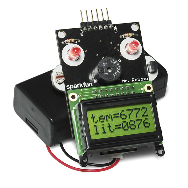
Meet Mr. Roboto! He's an Arduino-compatible development board designed to be used as a teaching tool for Arduino programming. All of the surface mount components come pre-soldered so a few minutes of simple through-hole soldering is all it takes to get him up and running. After the kit is put together, the on board sensors, buzzer and LCD screen make an excellent platform for learning how to write code for physical computing.
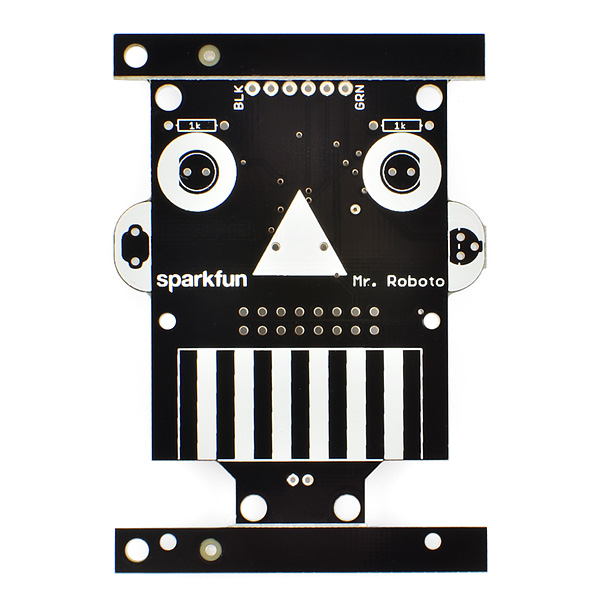
Mr. Roboto's "hair" is an FTDI programming header. Simply connect an FTDI breakout board and select "Arduino Pro or Pro Mini (5V, 16MHz) w/ ATMega328" under the boards menu in Arduino 1.0. Below, you'll find an archive of well-commented educational example sketches and an accompanying "readme" file describing what each one does in order of complexity. This board, combined with the example code which you can download below, is a great way to introduce students (or yourself) to physical computing and get started writing code. Thank you *very *much, Mr. Roboto!
Note: There is an error in the instructions. The instructions refer to a 10K resistor where it should be a 1K, which is included in the kit. Sorry about that!
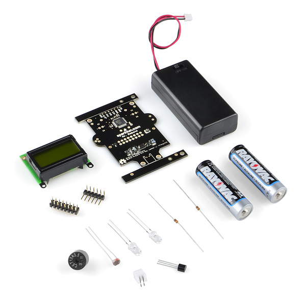
- Mr. Roboto PCB with Surface-Mount Components
- 1 x Mini LCD Screen
- 1 x 6-Pin Right-Angle Header
- 1 x 16-Pin Straight Header
- 2 x Super Bright Red LEDs
- 2 x 1kOhm Resistors
- 1 x Miniature Photocell
- 1 x TMP36 Temperature Sensor
- 1 x Piezo Buzzer
- 1 x 2-Pin JST Connector
- 2 x AA Batteries
- 1 x AA Bat tery Holder with Power Switch
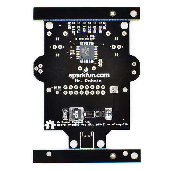
- ATMega328 running at 16MHz, Arduino compatible!
- On-Board Light and Temperature Sensors
- Piezo Buzzer and LCD Screen Provide Feedback
- Powered by 2 Included AA batteries
- Surface-Mount Components are Already Soldered
Comments
Looking for answers to technical questions?
We welcome your comments and suggestions below. However, if you are looking for solutions to technical questions please see our Technical Assistance page.
Customer Reviews
No reviews yet.
This is the lower cost answer to 7-segment shield I've been looking for! Has everything short of input buttons (which isn't much of an issue with the FTDI interface present).
By the way, any chance of Sparkfun selling these mini character LCD's by themselves? The 14x2 and 16x2 ones I'm using in my projects are an overkill most of the time.
I second the mini LCD request. The schematic makes it look like they are controlled over SPI? How much are they? For $5-10 a unit with SPI so I don't need to waste a bunch of I/O lines or pay a $10 premium for a serial LCD board, I'd buy some of these for all of my projects!
Pololu sells them
8*2 LCD
Futurlec
8*2 LCD
DigiKey
8*2 LCD
If sparkfun did sell them it would be nice. Third It!
They're definitely unique little LCDs; I like them. We'll check into selling them separately.
The controller is parallel only, just like our 16x2 and 20x4 LCDs (I can see the confusion - the ATmega's SPI pins are connected to some of the LCD control pins). Mr. Roboto drives the LCD in 4-bit parallel mode.
In fact, it uses the same HD44780-compatible display driver, as those larger LCDs. Which is really nice from a code perspective, because it just works with other Arduino LCD libraries.
I want to connect a smaller battery to my Mr. Roboto (e.g. LiPo). What specs does the battery need to have? Thx in advance.
Cool! Just about any single cell LiPo should work perfectly.
The NCP1402 step-up converter on Mr. Roboto can boost anything from about 0.8V-5V up to 5V. So, the 3.6~4.2V voltage range of a LiPo should work well with it.
Dang - Out of stock already!
nice little kit! first thought: feed a little PWM audio out the buzzer, call it a furby :D
I would love to see the same kit with buttons instead of temp and light sensing, so we could make things like metronomes, stopwatches, etc.
Better yet something slightly larger with a few proto areas on it ( like 4 x 10 pins ) so we could add the buttons or sensors of our our choosing.
Still pretty cool and cute.
Judging by the schematic LED's go through pairs of I/O pins and have resistors tying them to the ground. Looks like you could easily solder miniature bushbuttons in their place and have it working with minor code modifications.
Very cute! Looks like a nice beginner's kit.