- Home
- Product Categories
- Arduino Boards
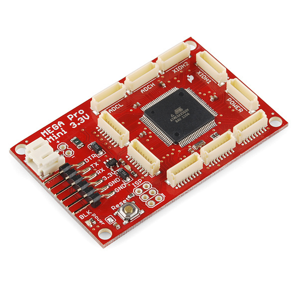
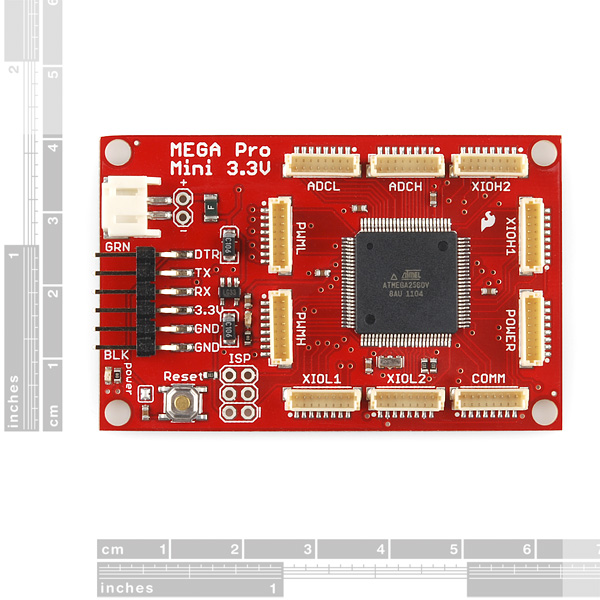
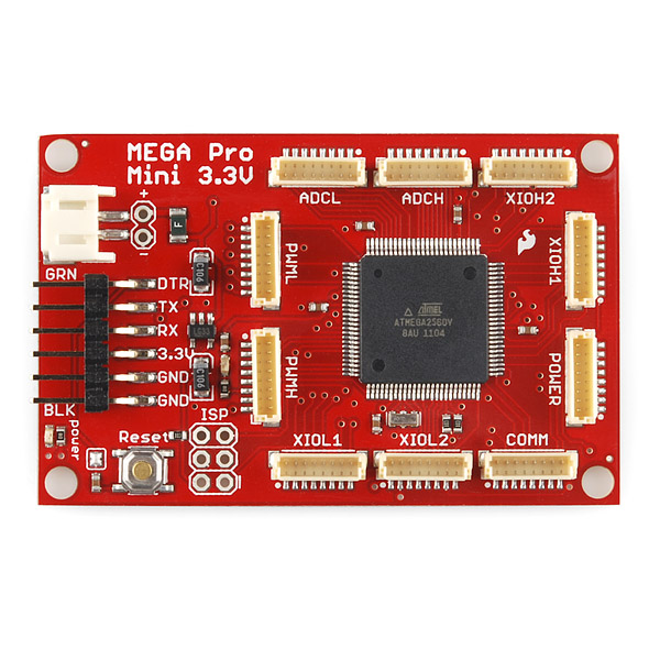
- Mega Pro Mini - 3.3V

Mega Pro Mini - 3.3V
Do you need "Mega" power in a "Mini" package? We can do that! We're continuing our Pro series of Arduino-compatible microcontrollers with the addition of the Mega Pro Mini. This is a 3.3V microcontroller running a version of the stk500v2 bootloader at 8MHz. In order to shrink the Mega Pro down to its minimum footprint, we've condensed the board layout, removed the barrel jack footprint and replaced the traditional Arduino-style headers with compact vertical JST connectors.
The Pro series is meant for users that understand the limitations of system voltage (3.3V), lack of connectors, and USB off board. This board connects directly to the FTDI Basic Breakout board and supports auto-reset.
Note: If you are using Arduino, modifications were made to the bootloader to support the 3.3V system, you will need to download and install a new board definition so that the Mega Pro can be programmed in the Arduino environment. The .zip archive below contains all of the files that you'll need including a "readme" file with simple instructions for how to install them. OR you can use Wiring and not worry about this since the board is officially supported.
Not sure which Arduino or Arduino-compatible board is right for you? Check out our Arduino Buying Guide!
- ATmega2560 running at 8MHz external resonator
- Low-voltage board needs no interfacing circuitry to popular 3.3V devices and modules (GPS, Accelerometers, sensors, etc)
- USB connection off board
- 3.3V regulator
- Over current protected
- Reverse polarity protected
- Resettable fuse prevents damage to board in case of short
- Schematic
- Eagle Files
- [Datasheet](http://cdn.sparkfun.com/datasheets/Components/General IC/2549S.pdf) (ATMEGA2560V-8AU)
- Board Definition Files (Arduino 1.0)
- Board Definition Files (Arduino 0022)
- Pinout Reference
- GitHub
Mega Pro Mini - 3.3V Product Help and Resources
Core Skill: Programming
If a board needs code or communicates somehow, you're going to need to know how to program or interface with it. The programming skill is all about communication and code.
Skill Level: Competent - The toolchain for programming is a bit more complex and will examples may not be explicitly provided for you. You will be required to have a fundamental knowledge of programming and be required to provide your own code. You may need to modify existing libraries or code to work with your specific hardware. Sensor and hardware interfaces will be SPI or I2C.
See all skill levels
Core Skill: Electrical Prototyping
If it requires power, you need to know how much, what all the pins do, and how to hook it up. You may need to reference datasheets, schematics, and know the ins and outs of electronics.
Skill Level: Competent - You will be required to reference a datasheet or schematic to know how to use a component. Your knowledge of a datasheet will only require basic features like power requirements, pinouts, or communications type. Also, you may need a power supply that?s greater than 12V or more than 1A worth of current.
See all skill levels
Comments
Looking for answers to technical questions?
We welcome your comments and suggestions below. However, if you are looking for solutions to technical questions please see our Technical Assistance page.
Customer Reviews
4 out of 5
Based on 1 ratings:
Make a 5V/16mhz version of this sucker, and I'll buy a bunch.
I'd totally appreciate that...
Same here, would love to have a 5V/16mhz one!
I would love that! Would buy too!
While the description says the board comes with a 8MHz external resonator, the processor isn't configured to actually use it (I measured it running at approximately 7.85MHz). The AVR pocket programmer isn't suited to flash this processor, but it can be used to read and write the fuse bytes.
The fuse bytes were set to L:0xE2, H:0xD4, E:0xFD, which means the processor is configured to use its internal oscillator. I set the low byte to 0xD6 (this sets the clock source to "Full Swing Oscillator; Start-up time: 258 CK + 65 ms; Ceramic res.; slowly rising power") and measured it running at 8MHz dead on.
I used the AVR pocket programmer for sale here on SparkFun. I soldered an ISP header onto the Mega Pro Mini board and connected the pocket programmer (pin 1 is marked on the Mega Pro Mini board, power the board with a separate power source). Then I used avrdude to read and write the fuse bytes. Write them with the following command:
IS there a mating connector for the port pins that could be used on a shield? By this I mean a surface-mount connector that would go on a shield board and plug into his board. I did some research on JST's web site but cannot seem to find one.
Hi, have you found anything? Having same issues here.
Does anybody know of a PCB-mounted female component that mates with these male JST-SH headers?
Hi, since it's been two years, have you found anything?
this looks great, way to shrink down the footprint
I was able to get this to upload under Arduino 1.6.4 by adding the following new section to my boards.txt file.
Can someone explain to me why the board has an 8MHz external resonator but has the fuse settings in the Arduino 1.0 boards.txt set to internal oscillator? Surely this makes the external resonator obsolete?
What is the typical power consumption for this board ?
Ordered two back on 6/21 and can only rarely get them to load with Arduino 0022 or Arduino 1.0. Sparkfun tech support has same issue, but no resolution yet, and say they may just give up and obsolete the board. I am a great Sparkfun customer, and I committed to a project that needs this board; super bummed!. Any ideas out there? Really appreciate any help.
I don't know if you've found a solution yet, but I also had the same problem when using the Sparkfun FTDI breakout. The way I got mine to work was to hold down the reset button right after clicking the upload button in the Arduino IDE, then releasing the button right before the IDE said "uploading." Don't know if you've tried that yet, but just a suggestion.
Anyone know the maximum voltage output of this board? I have a 5V motor driver. Not sure how to connect this to that...
anyone know the dimensions of this board?
Check out the Eagle files listed above. You can take the measurements of the board and also find the exact measurements of the mounting holes.
You guys planning to restock these? or get upgraded version? this is awesome concept, and I'd love to get my hands on one, but stock of 1 (at time of writing) makes me a bit nervous. Thanks.
If you get one of these, as I did, I suggest you put a drop or two of epoxy on the back side of the FTDI pins for programming (i.e. the 6 gold pins with .100" spacing).
One little tug of your programming adapter, and that connector comes right off the board as it is only surface mount soldered and there is no strong mechanical connection to hold it on.
This happened three times before I finally resoldered it and put the epoxy on it. Sparkfun: this should really be a through-hole connector, or glued on with epoxy, post soldering!
Very sorry about the problems you've had. It sounds like you received a poorly-attached part, please feel free to contact customer service if you find such problems in the future. We use and abuse our parts with this style of connector on a daily basis and rarely have this problem. Ensure that your FTDI/cable is not stressing the connector at a right angle, and as you say two drops of epoxy on the nubs on the back side of the board is good insurance.
PS: putting epoxy on the back of the board is not going to help- there's only a few mm of the connector there. It has to go near the SMT pads.
I respectfully disagree; if you consider the pads the pivot-point that the connector is rotating against (stressing and breaking the solder connections in the process), firmly attaching the plastic block holding the pins to the board will help resist this rotation. If you apply epoxy to the two indexing pins on the back of the board, it will wick into the gap between the pins and holes, hopefully providing a better connection.
But the earlier point stands; if you're not abnormally stressing this connector and it's breaking, contact our customer service department and we'll help you out.
Thanks for your reply.
I tend to think it is a mechanical design problem rather than a manufacturing error, as it came off too easily both times. All that is holding the current connector on there is six small smt solder pads, and two black dots of plastic (about 1mm in diameter) on the bottom of it. Give it a yank, and it comes off, taking the traces with it.
There are lots of epozy-type SMT adhesives around, why don't you investigate them? The mechanical reliability of this connector doesn't match the usual Sparkfun quality.
Could you guys update the Pinout Reference to reflect the cables currently sold?
If you actually read the datasheet (Figure 31-3. Maximum Frequency vs. VCC, ATmega640/ATmega1280/ATmega1281) , these atmegas are actually rated for something like 12Mhz at 3.3v. I think because all the baud calculations have been done for 8mhz, people are just lazy.
John Luciani did a bootloader for the atmega328 that supports 12mhz.... just sayin'
There are other considerations besides laziness; the clock math does work out very nicely for a number of timing applications besides serial, the slower you clock a microprocessor the less power it consumes (unused cycles beyond what your code requires are basically waste heat), you're that much further within the performance margins, etc.
Good night! This board should be powered by 3,7V LiPo battery? Thanks.
I can't quite see well enough, but is the JST looking connector on the left side the same size and type as the connectors you offer on your LiPro batts?
Yes. I've added some of the LiPos to the related items.
Hi Guys.. Has anyone actually tried to upload a bootloader to this micro from within arduino IDE.. Because I tried but I am getting the following error:
 ***failed;
avrdude: verification error, first mismatch at byte 0x0000
         0xcf != 0x0f
avrdude: verification error; content mismatch
I can confirm this issue: I have attempted for the past weekend to upload a bootloader to a custom Arduino Mega board I built, also running at 8 MHz. The full error appears immediately at the end of the bootloader burn processes. It is the exact same as the above and reads:
From reading and experimenting, it seems that this is a problem with the lock bits.
I have been able to upload sketches with my AVRISP mkII with no problem, and have also been able to upload the standard Aruduino Mega 16 MHz bootloader without this error (though of course it won't work -- was just testing to make the verification error go away). I have attempted to modify the makefile for the existing stk500v2 bootloader to include compatibility at 8 MHz, but so far have been unsuccessful -- the bootloader will upload successfully, but I will have timeout() errors when attempting to upload the sketch (so maybe something with the baud rate?).
For completeness, here is my attempt to change "Makefile" in the "stk500v2" directory of the Arduino source:
I haven't yet tried to burn a new bootloader to my Arduino Mega Pro 3.3V (I have the non-mini board but am posting here to keep the topic together) because I'm not sure whether it would be better to try on one of those boards or worse to possibly incapacitate my one USB-programmable system.
Clearly, someone at Sparkfun got this working for their boards, so I'm going to email their tech support and re-post with what we find out.
And in case it is useful, I am running Ubuntu 14.04, 64-bit, and am using Arduino 1.0.5.
My first thought: those are goinna be some interesting shield designs :)
I prefer something like this for the mini it's 5V not 3.3V though. Mega Cube
Is it possible to boost the speed of the processor up to 16MHz?
Possible? Yes. Suggested? No. 8MHz is the max for an atmega2560V, see page 369 of the atmega2560v datasheet for more info.
I always get so exited when I see connectors that look like SATA ones... but they never are... :-(
You should put the JST mini cable link into the description. http://www.sparkfun.com/products/10853
Cool small board! But why $20 more than the Mega Pro 3.3V? Are those JST headers very expensive?
They are, and it takes more time to populate, etc.
Have you guys had a look at Hirose DF-13 connectors? They are really great, we use 'em at work.