- Home
- Product Categories
- Battery
- SparkFun "Uh-oh" Battery Level Indicator Kit

SparkFun "Uh-oh" Battery Level Indicator Kit
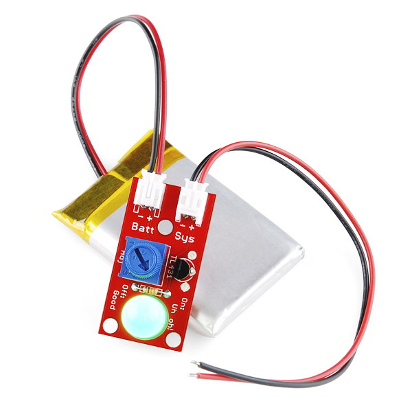
Under-powering a digital device can sometimes have pretty nasty consequences. Brown-out conditions can cause memory to get written or overwritten in odd ways, can cause unexpected behavior in connected systems and just generally screw up your day. One way to avoid this is to keep an eye on your battery voltage and turn off the system before it gets too low (or plug it in). We've whipped up a little board to help you out with this situation: the "Uh-oh" battery level indicator.
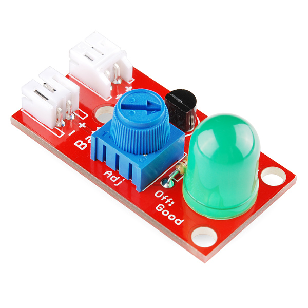
At the heart of the "Uh-oh" board is the TL431ACLPG shunt regulator diode. The reference voltage can be adjusted by using the trimpot on board. When the battery connected to the board reaches that voltage, the shunt allows current to flow through the LED, alerting you to a low battery situation. In order to set the appropriate reference voltage, you can use the formula found in the schematic to calculate your desired resistance and set it using the trimpot and a multimeter measuring resistance across the provided test points.
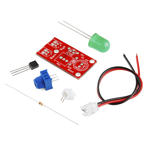
This board comes as a "bag of parts" kit. All of the parts are through-hole and it shouldn't take long to solder together. The footprint of each part is clearly marked on the PCB to help you throw it together.
- 'Uh-oh' Through-hole PCB
- 10mm Diffused Green LED
- JST Wire Assembly
- TL431ACLPG IC
- JST Right-Angle Connector
- 10K Trimpot
- 330 Ohm Resistor
- Schematic
- Eagle Files
- Datasheet (TL431ACLPG)
- Hookup Guide
- GitHub
SparkFun "Uh-oh" Battery Level Indicator Kit Product Help and Resources
Uh-Oh Battery Level Indicator Hookup Guide
April 9, 2014
Learn how to assemble and use the TL431 in the Uh-Oh Battery Level Indicator Kit.
Core Skill: Soldering
This skill defines how difficult the soldering is on a particular product. It might be a couple simple solder joints, or require special reflow tools.
Skill Level: Rookie - The number of pins increases, and you will have to determine polarity of components and some of the components might be a bit trickier or close together. You might need solder wick or flux.
See all skill levels
Core Skill: Electrical Prototyping
If it requires power, you need to know how much, what all the pins do, and how to hook it up. You may need to reference datasheets, schematics, and know the ins and outs of electronics.
Skill Level: Rookie - You may be required to know a bit more about the component, such as orientation, or how to hook it up, in addition to power requirements. You will need to understand polarized components.
See all skill levels
Comments
Looking for answers to technical questions?
We welcome your comments and suggestions below. However, if you are looking for solutions to technical questions please see our Technical Assistance page.
Customer Reviews
4 out of 5
Based on 1 ratings:
2 of 2 found this helpful:
Nice but.......
The only thing I have a problem with is the LED color. It probably should be Yellow, or even Red. Other than that it works well and it is very helpful, particularly with Lipo batteries that should not be allowed to discharge past a certain point.
Green? I'd expect "low battery" to have a yellow or red LED (to indicate "danger" :))
Nothing a quick DigiKey purchase can't solve
I originally picked a blue LED, but the forward voltage drop was too high. I then picked green because red seemed like a power LED to me. Green just says 'Uh-oh' to me. Your results may vary ;)
Indicating a "uh-oh" moment with a green LED is like telling someone their house is about to burn down with 2 thumbs up and a huge smile on your face.
yeah, or telling someones mother died by handing them balloons and a cake that says "sorry your mother died"
Does nobody recall the color of the "All systems Go!" light on the original GameBoy? RED. It was RED.
I forgot about that!! So true!! What about the gameboy color? I think that was red as well....
what about a blinking red LED? That would seem to be the easiest to get someone's attention...
6A li-po still ok with this?
Red is generally danger. It means the circuit is energized. Yellow/Amber is generally "alert".
You could add one yourself. It is entirely possible.
Yeah Green to me seems to be an "Everything is OK" indicator. Where as Red for me would be an "Everything is on fire" indicator. So, Yellow seems the best option*.
Tho either way its a nice little circuit and it introduced me to a component that I didn't know about that will be quite useful in the future :)
*I try to avoid blue LEDs personally because everyone I have run across seems to be one of those super blinding super bright LEDs. Tho had the current draw on the blue not been an issue it probably would have been an OK low battery indicator.
Any reason you couldn't solder onto the led pads to wire up an optoisolator? If so, couldn't a microcontroller read that as a button press?
had that same thought as i watched the video :D
Okay, for those of you that want to use a different color, a smaller LED (like I do) or some other indicator, here is what I found by studying the circuit and the data sheets. The way this works is that the TL431 looks like a 2.3 voltage drop when the voltage is above the reference voltage (se4t by the trimmer). When it enters the range below the reference voltage, the TL431 opens to allow any voltage (an open-circuit). So far so good. Now we need to have an indicator that operates in the voltage range between 2.5v and the reference voltage. The supplied LED starts to light at something like 3 volts. So it works just fine as long as the reference voltage is greater than 3 volts. Note that the intensity of the LED dims as you go from the reference voltage down to the operating voltage (a "turn-on" voltage if you wish.) After looking at several data sheets, I found that most LEDs operate at about 2.0 - 2.2 volts. Since this is below the TL431 minimum voltage, these LEDs are on all the time that a voltage above 2.0 volts is present. The indicator has to have a "turn-on" voltage between 2.5 and the reference voltage desired.
My simple solution was to add a pair of forward-biased 1N4148 diodes in series with the yellow LED which adds about a volt of voltage drop before a current can flow. This simple change allow the use of small (3mm) yellow LEDs in this circuit. Use the discussion above to adapt it to other indicators, just make sure the operating point is between 2.5 and the reference voltage that you want.
My LED is always on, turning the trimpot dims and brightens the LED on the other end. Any ideas on what is wrong?
I made a weird discovery with this kit... If you use the included big green gumdrop lookin' LED, everything works fine. But I bought some of the red and yellow gumdrop lookin' LEDs from sparkfun, thinking I'd just replace the green and be good to go. not so! With every LED besides the green one that came with the kit, it behaves like laptopman's kit. LED is on all the time and just dims and brightens in what seems like random spots on the trim pot, un-usable. but pop that green one on there and it works fine... i also have some blue LEDs i got from jameco, those work... but all the red, yellow, green, and amber ones I also got from jameco behave like the others, always lit, random dimming, etc... STRANGE! I thought LEDs were all the same, am i wrong? is this green LED somehow special?
It's the forward voltage drop..
I personally would use one of those trimpots that require a screwdriver to turn.
Is it possible to use a red 2.1 led rather than the green and if so what has to be changed?
This is a great product, but for my design I need an LED that can notify me of low 3.7 lipo battery for a while, so it needs to be very economical in it's power usage. Using a TS555 timer circuit, can I have it control an NPN transistor, only checking the battery once per second instead of constantly?
Does anyone know how much this kit (assembled) weighs? (preferably in grams) Thanks
Never mind... Posted on wrong product.
Looking at the data sheet, anew things occur to me... 1. Max charge current is 100 mA on USB power and 280 mA on DC power supply even though common 18650 lithium ion batteries have a max charge current of about 500 mA. 2. Suppose charging a lithium cell yields a 20% efficiency loss, then a 3000 mAh capacity Samsung lithium battery will take 36 hours on USB power or 12.9 hours on DC power.
Am I looking at this right?
I've used it for my GPS datalogger project and found some effect that I want to describe. Uh-oh was placed between battery and Powercell (charger + 5v source). When I disconnect the drained battery from Uh-oh (to prevent full discharge with Oh-oh green LED) and put the external power on Powercell USB connector to feed the device, Powercell turns on the red LED, indicating battery charging process (while there is only Uh-oh on battery connector).
So, if you are going to put the Uh-oh between the Powercell (or some other LiPo charger) and battery, it's better to use double switch to cut off both inputs of Uh-oh.
I want to use something like this as a voltage monitor, where if the voltage is above 5.7V, I get a green light, and if it drops to 5.7V or below, the light goes out, do you have something like this? I am worried that if there was no power to this device, it would give a false positive.
ive made about 4 low-battery indicator circuits, through-hole, and 2 using SMD parts, Green LED lights up and stays on when power is good and a red LED lights up when the power drops below the set level and the green LED goes out !
http://www.daftmike.com/2010/03/my-low-battery-indicator-circuit_22.html
very nice little circuit and using real easy and common components !
Oh btw, i used a much higher resistor for the LED's so that they use less power when in operation !
hope this helps !
Would this work with a 12v battery i have? It is essentially just 8 aa wired together.
We have a standard for these things- the world has agreed that STOPlights are red, and green means GO. Green- go; Red- stop. Its planetwide at this point. I'd be using a red LED- amber or yellow would be okay too.
Can you hookup a charger through this? or will this device mess with the charge process?
would it be possible to use the same components and have the LED on all the time and then go off when the voltage gets low?
From the schematic is states that the LED should have a forward voltage drop of 2.5, I'm not sure where this comes from (if someone could tell me I would appreciate that), but surely the level that you want to indicate low batter is effected by the LED voltage drop. That is you cannot have a voltage level below the LED voltage drop or the LED will not allow current to run. For example if you have LED voltage drop is 3.4 volts then you cannot have a level indicator below this. I think this is correct.
Nate, I don't follow how you define Vref @ 2.5V can you explain that please?
It's declared in the TL431 datasheet.
Would be great if they made a second version of it which actually cut the load off if there is under voltage..
I have a Data Logger project that I have been working on for a while. I kept breaking SD cards when my battery got low enough for the arduino to start acting funny. So what I did was used this UH-OH battery to be a voltage detector. I actually took the LED out of the board and have the LED terminals wired back to a digital input on my arduino uno, so when my battery dips to a certain voltage, say 6.5V when i am using a 9V supply, it flags a bit to stop running my arduino project, so I don't kill any more SD cards.
I'm making a sump pump battery backup system using a Netduino Plus. Can I use this to monitor deep cycle AMG batteries?
If this is on all the time, rather than switched in occasionally, it will contribute to current drain and therefore flatten the battery quicker. This may not be too much of a problem with high capacity batteries, but will be with some. A low current comparator or something like that would have been a far better design than what is effectively a shunt regulator that will drain a relatively high current.
I redesigned this to be much smaller a while ago (My application required smaller parts), and I only fired this thing up every 30 seconds from an Arduino, returning a bit of data to represent the status of the battery (Is it low? If so, return 1). The same thing can be done with this, if you just connect the VCC to an output pin rather than to the battery directly.
Yeah, that's a good idea, keep the drain to a limited time.
could this be used with 11.1 lipo
I'd use a red blinking LED myself. Digikey 67-1499-ND (5mm) at 3V or Newark L-796BID (8mm) at 3.5V. Probably won't work so well with a single-cell LiPo though.
I was thinking that too. I don't see why not; worth a shot for $6!
Judging by the formula and the size of the pot it looks like this could be used to "Uh-Oh" large batteries, say and 18.6 LiPo, with cutoff set at 14.4V or something like that. Is this in fact the case, or am I perhaps mistaken?? Thanks!
Current with LED off should be about 5 mA with a 3.7V battery level.