- Home
- Product Categories
- Raspberry Pi
- RaspiRobot Board

RaspiRobot Board
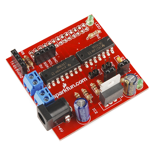
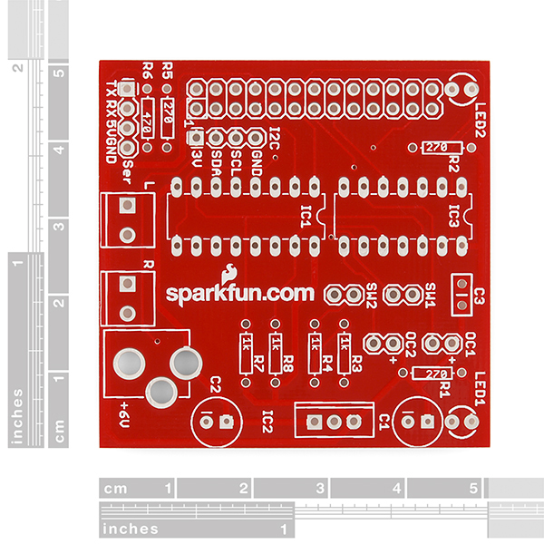
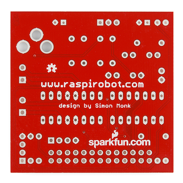
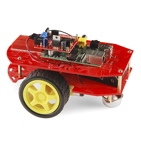
The Raspberry Pi packs plenty of processing power in a small and inexpensive package and that makes it perfect for robot brains! The only problem? The Raspberry Pi may have plenty of low-level hardware peripherals but motor controllers aren't one of them. That's why the RaspiRobot project got started. The RaspiRobot board is an expansion board for the Pi that turns it into a robot controller.
The board comes as a kit of through-hole parts which is easy to assemble with even a basic soldering iron and limited soldering experience. A step-by-step assembly guide is available to help you through the process.
After you've assembled it, simply plug the RaspiRobot Board into the GPIO port on the Raspberry Pi and it provides dual bi-directional motor controllers, two open collector outputs, two switch inputs, a pair of status LEDs and even a voltage regulator capable of powering the Pi using a battery source from 7-12VDC.
A Python library module makes it easy to interface with the robot hardware from your software on the Pi. The combination of Raspberry PI and the RaspiRobot Board makes it easier and more affordable than you might think to build a robot with computer vision, web access or even machine learning using the linux operating system and Python code.
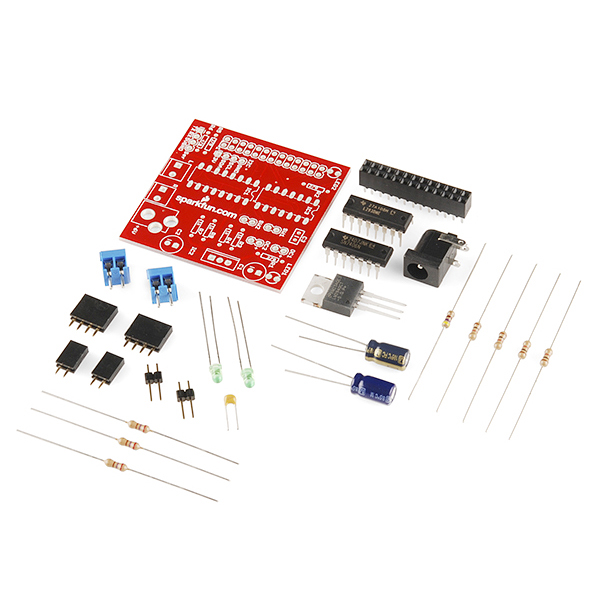
- RaspiRobot Board PCB
- 1 x L293DNE 4-Channel Motor Driver
- 1 x SN7406N Hex Inverter Buffer/Driver
- 1 x LM2940 Voltage Regulator
- 3 x 270 Ohm Resistors
- 1 x 470 Ohm Resistor
- 4 x 1K Resistors
- 1 x 220uF Capacitor
- 1 x 100uF Capacitor
- 1 x 0.1uF Capacitor
- 2 x Green 3mm LEDs
- 2 x 2-Pin Female Headers
- 2 x Male Pin Headers
- 2 x 4-Pin Female Headers
- 1 x Female Header 2x13
- 2 x 2-Pin 3.5mm Screw Terminals
- 1 x DC Barrel Jack Connector
- Dual Bi-directional Motor Control
- Voltage Regulator powers Raspberry Pi from Batteries (7-12V)
- 2 x Open collector outputs (25mA)
- 2 x LEDs
- 2 x Switch inputs
- 5V Serial connector
- 3.3V I2C connector
- Simple to use Python library module
- Schematic
- Eagle Files
- Assembly Instructions
- Datasheet (L293DNE)
- Datasheet (SN7406N)
- Python Library
- GitHub
RaspiRobot Board Product Help and Resources
Core Skill: Soldering
This skill defines how difficult the soldering is on a particular product. It might be a couple simple solder joints, or require special reflow tools.
Skill Level: Rookie - The number of pins increases, and you will have to determine polarity of components and some of the components might be a bit trickier or close together. You might need solder wick or flux.
See all skill levels
Core Skill: Robotics
This skill concerns mechanical and robotics knowledge. You may need to know how mechanical parts interact, how motors work, or how to use motor drivers and controllers.
Skill Level: Rookie - You will be required to know some basics about motors, basic motor drivers and how simple robotic motion can be accomplished.
See all skill levels
Core Skill: DIY
Whether it's for assembling a kit, hacking an enclosure, or creating your own parts; the DIY skill is all about knowing how to use tools and the techniques associated with them.
Skill Level: Noob - Basic assembly is required. You may need to provide your own basic tools like a screwdriver, hammer or scissors. Power tools or custom parts are not required. Instructions will be included and easy to follow. Sewing may be required, but only with included patterns.
See all skill levels
Core Skill: Programming
If a board needs code or communicates somehow, you're going to need to know how to program or interface with it. The programming skill is all about communication and code.
Skill Level: Competent - The toolchain for programming is a bit more complex and will examples may not be explicitly provided for you. You will be required to have a fundamental knowledge of programming and be required to provide your own code. You may need to modify existing libraries or code to work with your specific hardware. Sensor and hardware interfaces will be SPI or I2C.
See all skill levels
Core Skill: Electrical Prototyping
If it requires power, you need to know how much, what all the pins do, and how to hook it up. You may need to reference datasheets, schematics, and know the ins and outs of electronics.
Skill Level: Competent - You will be required to reference a datasheet or schematic to know how to use a component. Your knowledge of a datasheet will only require basic features like power requirements, pinouts, or communications type. Also, you may need a power supply that?s greater than 12V or more than 1A worth of current.
See all skill levels
Comments
Looking for answers to technical questions?
We welcome your comments and suggestions below. However, if you are looking for solutions to technical questions please see our Technical Assistance page.
Customer Reviews
No reviews yet.
Hi, I found that my raspirobot v1 works just fine without the Voltage Regulator element (LM2940). Is it risky? How is that possible?
And it seems like the side effect is that it does not drain the batteries so fast. Is that possible?
https://twitter.com/4cd/status/850989300216991745/photo/1
https://www.youtube.com/watch?v=LGxheRNw4z4
Does anyone have one of these and an oscilloscope? The supply bypassing seems marginal for a device switching power:
1). The lack of ceramic bypass on the Vin line could increase noise on the wiring. Risk is radiated EMI exceeding FCC limits. Maybe slow switching of the L293D mitigates.
2). Unless it's a premium grade part, the 100uF regulator output cap may not meet the ESR requirements over component variation, temperature and aging. Risk is low level oscillations increasing noise and power losses.
I tried to use the nodejs package but no luck. I'm sure that the board is working because I tested with the Python library. Anyone have tested this package?
Hi, I am getting the following error on B+ with the code for the raspirobot. Can anyone please help
Any chance of getting version two of these in stock?
I'm not sure what you mean by version two. If you can explain a bit more clearly, we can see what we can do!
https://www.adafruit.com/product/1940
Ah, ok. That's actually designed by someone else, so our v2 wouldn't necessarily match up with that. If there are features you guys want to see though, please let us know. Customer feedback helps us really improve designs when doing revs.
"A step-by-step assembly guide is available to help you through the process." And where would that be?
It's the RaspiRobot site linked above. Sorry for the confusion!
This turned out to be a pretty decent purchase. I had to heat sink the Vreg to get my setup functioning properly, however.
does it matter if i accidentally solder the components to the wrong side of the board so everything is flipped around?
You can run into problems doing this as some parts can't be inserted backwards. If you've already done this, you need to really look at the caps and the ICs on the board. Those are going to be the most likely places to cause you problems.
I am running into an issue with the board, but am not sure where to look further... I have it connected to the PI and am powering the PI via usb power.... when I run through the test commands, I can turn the LEDs off and on, but when I try to have the motors go, I am not getting any power to the motors. Would this be because I don't have enough power on the robot board and should be running power there vs the PI?
You got it. USB very rarely can source enough current to drive your system as well as motors (not just for Pi, but in general). I would recommend an external power source and see if that helps.
Does anyone have samples of code and/or wiring diagrams for using this board with a 2-coil stepper motor?
I would like to know what is the positive and negative of the 6v power supply? Positive is the interior or exterior?
Center positive - if you check the schematic, it's indicated on the left hand side. It's also practically the only way anybody sane should be wiring barrel jacks for new products (and SFE are doing their part). If you come across a center negative one not designed for a pre-existing application that has a center-negative power supply, send the designer a scathing e-mail and consider alternatives ;) (That said, it couldn't hurt to include polarity information on the silkscreen.)
Awesome!. Thanks for the answering the same question I came here to find out..
While an LM323T would work, it can drop down to 4.55V at full load; that's going to cause the RPi to reset the first time the motors stall out. A much better solution would be a UCC383T-5, which has an ultra low dropout of 0.45V@3A, so you can use a 7.2V Li-Ion pack; it's also got a minimum voltage of 4.85V at load, so no worries about the Pi staying up. It's pin compatible with the LM2940 and will function just fine with the RaspiRobot's input and output filters. You can even get one as a sample from TI, so there's really no reason not to give it a try.
which capacitor should i use with the UCC383T? could not find anything on the datasheet.
So I got my kit put together (it was missing the SW1 & 2 headers, BTW) and hooked it up to power my RPi. I fed it 9v from a bench supply. The RPi never booted and the regulator got hot enough to cook my finger when I touched it.
To make a long story short, the regulator only puts out 1 amp. That's hardly enough to run a bare RPi. If you add accessories (wifi adapter, USB hard drive, etc.) it's not enough for even the RPi. There's certainly nothing left over for the motors.
Looks like I'll have to remove the regulator circuit and feed it 5v from a real power supply instead of the toy one on the board.
I believe you and the people replying to your post missed the fact that the motor power (volts/amps) is taken directly from the battery. If you noticed the schematic Vin feeds the Vreg as well as the L293 motor voltage. I will agree that an amp is really only meant to offer power to a bare RPi, and, a heatsink probably should have been included with the Vreg. Swapping for a higher current Vreg is definitely the easiest solution. Replacing the RPi's terribly inefficient Vreg would be another option, but, nowhere near as easy as installing a higher rated, pin compatible Vreg on the addon board.
I went ahead and yanked that wimpy regulator, connected the input to output and fed the board with 5V. Everything worked great. Some measurements showed that with both motors running, along with the wifi and the USB hard drive, the system was pulling 1.6 amps, well above the capability of the Raspirobot's regulator even with a heatsink. By turning off the LEDs and the hard drive, current consumption dropped to 1.2 amps with both motors freely running. The lowest I saw was 900 mA with the motors off, the wifi running and the disk inactive. In short, this board is marginal or inadequate for powering a robot and the RPi. I'd recommend using an LM323T regulator instead. It's pin compatible and will handle up to 3 amps. At 1.6 amps it will be cruising, even without a heatsink.
As far as why I have a USB hard drive - the SD card is a miserable choice for a hard drive substitute. The write times are slow and non-deterministic and it is prone to corruption. SD cards were designed to hold pictures in camera, not to be operated as general purpose read-write drives. In my setup, I've modified the kernel parameters in cmdline.txt and some startup files so that the RPi boots from the SD (in read-only mode), then mounts its root file system from the hard drive. That gives me fast, reliable storage with no chance of SD card corruption. But it does add 200 ma or so to the power budget, as well as moving parts.
For the final robot, I'll be using a RAM disk-based system where the SD card will be the boot device and the root file system will be mounted on a RAM disk loaded once from the SD card. But this means that I won't be able to use Raspbian because it's too bloated. This will require a custom-built distro. I've done this on x86 and gotten the kernel, root file system and app into 6 MB. With this approach, there will be no moving parts, no chance for SD card corruption and minimal power consumption.
Cheers all.
Got an even better power solution. While replacing the regulator with an LM323T did let me get enough current, the batteries kept dying in minutes. So I got a DC-DC convertor for $6.95 from a surplus place (18->36V in, 5V out at up to 6A) and hooked it up to a lithium ion cordless tool battery (DeWalt, 20V, 1.5 AH). I just now finished a test run with the RPi, the wifi, the USB hard drive and both motors running continuously for 1/2 hour. Total time on the battery is about 1 hour, with about 40 minutes motor time, and it still has plenty of juice.
If I did my math right, the battery has 27WH out which the convertor turns into 22WH. At 8 watts for the robot with both motors on, that turns into almost 3 hours continuous operation with both motors on. Of course, there's the battery's discharge curve, the convertor's input threshold, etc. to consider, but even so there's a good chunk of operating time available, especially if the motors are not running full time. And as I said, I just finished a 1/2 hour continuous run, so that much is empirically demonstrated.
Just for the fun of it, I'm writing this on the robot. I'm logged in through vnc and using the robot as a web browser. There's something very amusing about that.
Anyway, the RaspiRobot board is a great toy once the power issues are fixed.
cheers
I had a wonderful time setting this up; no problem. I composed a blog in case setting up all the code was confusing http://jmd.dev4.webenabled.net/node/88
The kit was missing the 2 x 2-pin female headers. Luckily I had them on hand; otherwise it went together just fine. (If that is unavailable, then it needs to have 4 each 4-socket headers; 2 of them must then be cut up to make 2-socket headers (which always sacrifices a pin in the process).
I am unable to find out about assembling or the parts for the range finder serial adapter for the RaspiRobotAny ideas please.John.Qld.Aust
Oh, how long awaited you have been!!!
todo list-- 1) Add to cart--Check!!!
Semi-pro, type "uname -a" at a command line and it will tell you which kernel you are running. If the kernel builder felt like following naming conventions, there will be all sorts of good data there. When I do it I get:
"Linux raspberrypi 3.2.27+ #250 PREEMPT Thu Oct 18 19:03:02 BST 2012 armv6l GNU/Linux"
which tells me, among other things, that the kernel was built with pre-emption. You can verify this by unpacking /proc/config.gz and searching for the word "PREEMPT" under "Kernel Features". Mine has "CONFIG_PREEMPT=y", indicating that kernel pre-emption really is turned on. So this should not be an issue.
What's more of a problem is that the library is written in python which, like all interpreted languages, is a miserable choice for hard real time applications. On the other hand, it's perfectly good for testing the hardware connections and documenting the necessary algorithms. Once the hardware is tested and the algorithms understood, the real code can be written in something like C or C++ for actual use.
You'll still have to adjust priorities and niceness, but you'd have to do that with any application.
Have fun.
Wrong again. PREEMPT and PREEMPT_RT are 2 different things. Moreover, I guarantee you that even with RT_Linux you can't do much about it. You gotta use something like Xenomai to get the most of your Linux kernel in terms of real time. Forget about PREEMPT and PREEMPT_RT.
Let me put it this way. I used bit banging (on a different board/proc) to drive the quad stepper controller sold by Sparkfun. In non real-time, everything went smoothly as long as I didn't do anything else with the board. In fact, even the simple sending of a character through the serial console made the stepper stutter. With Xenomai installed, I could run the stepper at 250 RPM in full step without any problems.
Using GPIOs for driving servos/steppers without real-time preemption is pointless.
Try the following approaches:
1) start your servo program 2) nothing else runs on the board
approach #2: 1) start your servo program 2) launch a program that does some random stuff (loops/math whatever).
Conclusion: unless your kernel has been compiled with some sort of real-time extension, you can't trust that library which, as far as I can tell, is simple bit banging. Also, if you just wanted to do something that circumvented the real-time issue, use the hardware paripherals on the Broadcom chip.
Check out a software package called ServoBlaster. It moves some of the servo PWM off the CPU and uses hardware peripherals to generate a much nicer servo PWM. Supports up to 8 servos.
The software teachop linked (pi-blaster) is literally a fork of ServerBlaster... :)
For the record, yes it works very nicely! I've done some tests using it to drive several motors with my own hardware and there's no interruption, even when I spike the CPU to nearly 100%!
This provided code appears simple, turning a bridge on or off with no PWM or stepper feature. Precise timing was probably not the target. If you wanted to try some stable PWM type of control would this approach work:
http://blog.makezine.com/2013/02/12/pi-blaster-improves-software-pwm-on-raspberry-pi/
yeah,
ive tried doing some bit-banging from the kernel level, and it maxed out at 20mhz if i disable all scheduling/interupts (didnt measure jitter)
i think it was 10mhz or less if i ran a schedule() call between every toggle of the pin, so best case, it will randomly hang in the current state for 1/10,000,000th of a second or more
and things will only get worse as you try to run any load
I had been looking to make my own version of something like this. Glad I wasn't the only one thinking about this. I will probably grab one of these in the meantime. Maybe use some of these ideas later in my own board.