- Home
- Product Categories
- GPS Boards
- SparkFun GPS Module - Copernicus II DIP (12 Channel)

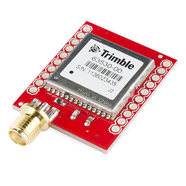
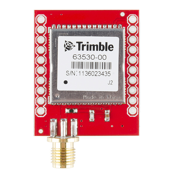
SparkFun GPS Module - Copernicus II DIP (12 Channel)
The Copernicus II is a great GPS module from Trimble, but the SMD module prohibits immediate gratification. This DIP allows the customer to gain direct access to the pins on the SMD module. Simply provide 2.7 - 3.3VDC. The Copernicus II DIP breakout has an impedance-matched, end-launch, standard SMA connector that will mate with our SMA GPS antennas listed below.
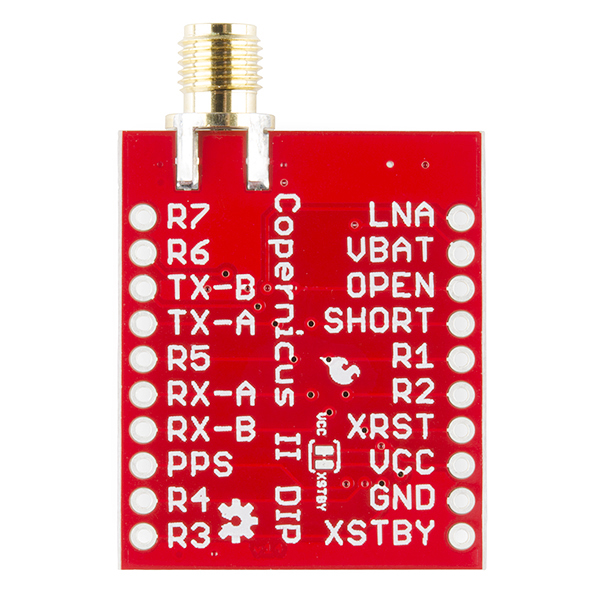
This revision of the board fixes a few silkscreen errors and adds a jumper between the VCC and XSTBY pins.
Not sure which GPS module is right for you? Check out our GPS Buying Guide!
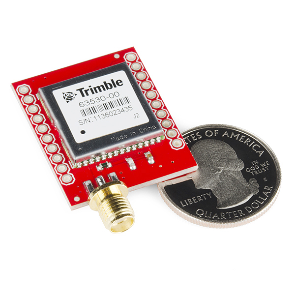
- Board Dimensions: 1.1 x 1.25"
- 0.9" between pins (bread board friendly)
SparkFun GPS Module - Copernicus II DIP (12 Channel) Product Help and Resources
Copernicus II Hookup Guide
December 18, 2013
A guide for how to get started with the Copernicus II GPS module.
GPS Basics
December 14, 2012
The Global Positioning System (GPS) is an engineering marvel that we all have access to for a relatively low cost and no subscription fee. With the correct hardware and minimal effort, you can determine your position and time almost anywhere on the globe.
Core Skill: Soldering
This skill defines how difficult the soldering is on a particular product. It might be a couple simple solder joints, or require special reflow tools.
Skill Level: Noob - Some basic soldering is required, but it is limited to a just a few pins, basic through-hole soldering, and couple (if any) polarized components. A basic soldering iron is all you should need.
See all skill levels
Core Skill: Programming
If a board needs code or communicates somehow, you're going to need to know how to program or interface with it. The programming skill is all about communication and code.
Skill Level: Rookie - You will need a better fundamental understand of what code is, and how it works. You will be using beginner-level software and development tools like Arduino. You will be dealing directly with code, but numerous examples and libraries are available. Sensors or shields will communicate with serial or TTL.
See all skill levels
Core Skill: Electrical Prototyping
If it requires power, you need to know how much, what all the pins do, and how to hook it up. You may need to reference datasheets, schematics, and know the ins and outs of electronics.
Skill Level: Competent - You will be required to reference a datasheet or schematic to know how to use a component. Your knowledge of a datasheet will only require basic features like power requirements, pinouts, or communications type. Also, you may need a power supply that?s greater than 12V or more than 1A worth of current.
See all skill levels
Comments
Looking for answers to technical questions?
We welcome your comments and suggestions below. However, if you are looking for solutions to technical questions please see our Technical Assistance page.
Customer Reviews
3.7 out of 5
Based on 3 ratings:
1 of 1 found this helpful:
Good Performance GPS chip
This module performs exactly as per specs, it is ease to interface and very sensitive. My only remark is that the module does not allow the antenna to be fed independently. That would allow antenna current sensing, among other possibilities.
Link to Trimble GPS Studio is Dead!
Looks like the link to the Trimble GPS Studio is dead and I can't seem to find it on Trimble's Site!
The Trimble Studio & Support Tools link doesn't go to a site, but rather, downloads a zip file containing Trimble Studio. If you've clicked it, check your download folder for a compressed file named "TrimbleStudio_V1-64-00". Unzip that, and you should be all set to go! Happy Hacking!
Please note the current download link is not active anymore. They are currently making many improvements to the tool, including an update in April. Here is the link I used to download the latest version. http://trl.trimble.com/dscgi/ds.py/Get/File-484972/TrimbleStudio.exe
This module can be combined with a Raspberry Pi, antenna, and 5 wires to create your own NTP server with excellent accuracy, by following the common tutorials around the Internet. If the PPS signal does not appear to be working, try increasing the PPS signal duration from its default 4200ns to 42000ns using the Trimble Studio software. A 4200ns pulse appears to be too fast for the RPi to notice.
Integrating this module in a new application. SparkFun makes this SUPER easy! Minor Notes: The Trimble Studio Link above is stale: new link http://www.trimble.com/embeddedsystems/copernicus2.aspx?dtID=support
Future requests: 1. optional pad for an MCX connector instead of the SMA 2. silk screen for some of the pads on the same side as the chip (once it was mounted to the bread board it was hard to probe 3. [ALTERNATE] bring Vcc, GND, TXB, RXB to board edge opposite the antenna
Otherwise, super pleased!
I'm struggling to get any coordinates from GGA (latitude, longitude, UTC time, ect.). I have the latest Copernicus II DIP Module and tried to hook it up similar to how the hookup guide does it in the link (https://learn.sparkfun.com/tutorials/copernicus-ii-hookup-guide/all), but I am only getting the NMEA format with no numerical data displayed on my terminal, Tera Term. I've connected TX-B and RX-B to the breakout with a 4800 baud rate and checked that 3.3 V was the voltage going into the module. It says on the terminal that my GPS Quality has an invalid fix and the mode indicator (VTG) says that the data is not valid. Is it not in run mode? Is there a pin that needs to be held high that the hookup guide does not show or that I have just forgot? Any help would be greatly appreciated!
I've created an Arduino library for this module, now available here: https://github.com/trbabb/copernicus
The module implements the powerful TSIP binary interface, and includes an example sketch. This should make getting the GPS up and running a lot simpler, especially if you need to get at some of its more advanced features.
cheers!
Awesome! Would you mind if we added your library to our GitHub repository (it's linked above in the Documents section)?
~~Yep, go right ahead!~~ Actually, how about a link to the source repository? That way the two won't get out of sync when updates are made.
We could do either. If you'd rather not have your code modified by other SFE users and possibly added into the repository at a later date, we can just do a link.
The main thing is that I'd like changes/improvements made by other users to make their way into the original branch, and vice versa, rather than dev happening in two places. In other words, I don't want to have to keep copying back improvements from SF, or if I make improvements, I don't want yours to fall behind. If there's a way to arrange that, I'm happy! (Sounded like it was just going to be duplicated over, but maybe it can be branched into your repo? I'm still somewhat new to GitHub, so apologies if that's what you meant).
I'll take a look into it and see what we can do. I totally understand not wanting to let the two versions get out of sync, and that's a good consideration for sharing the information. Thanks!
I'm having a hard time get a fix with this GPS. I'm configured to use TAIP, and all queries to the GPS return <RXX ... 0000 ... >. I'm using the following antenna: https://www.sparkfun.com/products/177 and I connected the GPS/Antenna with a separated Power Supply.
This is my following setup: XSTBY --> Vcc OPEN --> GND VBAT --> Vcc The rest of the pins are unconnected.
Any ideas why is not working??
I know it has been 8 months but I am trying to change mine over from TSIP to TAIP and can't figure out how to structure the command. If you still have your code could you give me any pointers?
My first thought would be that your power supply can't source enough current. This is a pretty common error that occurs with a weak power supply. Double check that, and if you are still having problems, contact techsupport@sparkfun and they can help you out further.
What antenna can I use with this?
Cheers!
This one works well.
Thanks a bunch!
I have an early copernicus II module, but cannot talk to it. I have worked through the tutorial l using a USB breakout set for 3.3v and tried Tera Term on a PC and coolterm on a MAC. In both cases I can connect TX to RX and see stuff I type on the keyboard echoed back to the terminal screen. However when I connect to either TX-B and RX-B or TX-A and RX-A nothing shows on the terminal screen. I have an active antenna connected, I am doing my test setup in side a house so reception will be a bit iffy, but I reckon I should see something. Apologies if this comment should be posted somewhere else.
Any thoughts or suggestions welcome.
Peter_B.
Try to figure out what version you have and double check the schematic of the previous version (linked above). There were pin connection changes, so you could potentially have a version which requires a different connection.
Thanks to the persistent Allison in Tech support I now have a working Copernicus II, my unit was a very old version and it needed to have XSTBY, BOOT, XRST & R2 all tied to VCC. Then it came to life and started sending out NMEA sentences.
To Toni_K Thanks for your interest. It did indeed turn out to be pin connection changes that were needed.
Glad to hear Allison was able to help you out and you now have a working unit. Have fun playing :)
similar problem... Antenna connected ... tx-b pin 3... rx-b pin2... vcc @3.3, gnd to pwr-gnd and pin5... xstdby to vcc. not seeing anything via hyperterm.
swapped in null modem just in case. still nothing out.
Oscope can see tx data burst, but Hyperterm @4800 doesn't show anything. not even garbage. does anyone else have this module working?
This module works, I verified operation for both A (115200 baud) and B (4800 baud). I tested on windows with putty and mac osx with coolterm.
Does this revision fix the RF impedance issued mentioned by John Beans in the previous product page: https://www.sparkfun.com/products/11067
Both layouts appear to be 50 mil. The trace length is around 140 mil for both. This gives an impedance of roughly 75 ohms. The RF Input on the Copernicus is a 50 ohm input however. The trace width needs to be wider for 0.064" thickness with 1 oz copper thickness. Am I missing something here?
I've attached screenshot of existing setup: http://imgur.com/yEvXdVo
I've attached screenshot of what I think is a properly sized transmission line: http://imgur.com/msl875R
GPS L1 power on the reciever is very low, like attowatts. The signal is literally below the noise floor so decibels really matter here, so losing 50% of the power is a big deal.
It looks to me that the module uses a grounded coplanar wave guide and not a microstrip. If you re-run your calculation with a 50 mil trace and 10 mil clearance between signal trace and ground you should get approximately 50 ohms. http://i.imgur.com/sEpKPAK.png
I checked the Eagle files. This module is using a grounded co-planar wave guide but "S" (the spacing between the signal trace and the top-layer ground) is 12 mil instead of 10. This works out to an impedance of 52.8 Ohms. It would have been better if the spacing was 10 mil, but still a LOT better than 70 - 80 Ohms!
It still cant work. I set the pin as http://i.imgur.com/JW0EGNf.jpg, and link pin R2 to Vcc(3.3V) but it still cant work.
Hi, I have buy this Eval Boards GPS11858. I link the pin : pin------>input/output VCC---->power 3.3V GND---->power ground TXA----->RS232 TXB----->RS232
It will return message, but without the GPS data. Anyone can help me?
Any idea if this has the ITAR limitations on it?
If you're talking about the speed and altitude limitations that all consumer GPS receivers have built into them, than yes, this has those limits.
It does implement those limits as AND rather than OR, so apparently in "AIR" mode it will work up to 50,000m as long as you are going slower than 515 m/s