
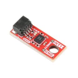
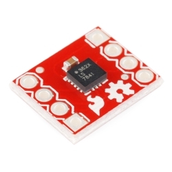
SparkFun Triple Axis Accelerometer Breakout - ADXL345
Helpful Documentation
 Hookup Guide
 Schematic
 Datasheet
Product Overview
This new version adds 2 standoff holes as well as an extra decoupling capacitor. The ADXL345 is a small, thin, low power, 3-axis MEMS accelerometer with high resolution (13-bit) measurement at up to +-16 g. Digital output data is formatted as 16-bit twos complement and is accessible through either a SPI (3- or 4-wire) or I2C digital interface.
The ADXL345 is well suited to measures the static acceleration of gravity in tilt-sensing applications, as well as dynamic acceleration resulting from motion or shock. Its high resolution (4 mg/LSB) enables measurement of inclination changes less than 1.0 degrees;.
Several special sensing functions are provided. Activity and inactivity sensing detect the presence or lack of motion and if the acceleration on any axis exceeds a user-set level. Tap sensing detects single and double taps. Free-fall sensing detects if the device is falling. These functions can be mapped to one of two interrupt output pins. An integrated, patent pending 32-level first in, first out (FIFO) buffer can be used to store data to minimize host processor intervention. Low power modes enable intelligent motion-based power management with threshold sensing and active acceleration measurement at extremely low power dissipation.
Features:
- 2.0-3.6VDC Supply Voltage
- Ultra Low Power: 40uA in measurement mode, 0.1uA in standby@ 2.5V
- Tap/Double Tap Detection
- Free-Fall Detection
- SPI and I2C interfaces
Documents:
- Schematic
- Eagle Files
- Hookup Guide
- Datasheet
- Example Code (ATmega328)
- GitHub


-
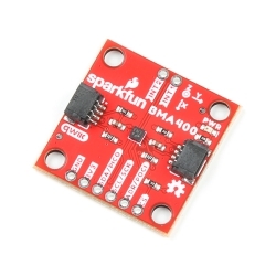
 3-Axis MEMS Accelerometer - MMA8452Q
Special Price Current price: $1.49 Regular Price Original price: $2.95In stock
3-Axis MEMS Accelerometer - MMA8452Q
Special Price Current price: $1.49 Regular Price Original price: $2.95In stock -
-
-


Features & Specs
- 2.0-3.6VDC Supply Voltage
- Ultra Low Power: 40uA in measurement mode, 0.1uA in standby@ 2.5V
- Tap/Double Tap Detection
- Free-Fall Detection
- SPI and I2C interfaces
Documentation
- Schematic
- Eagle Files
- Hookup Guide
- Datasheet
- Example Code (ATmega328)
- GitHub
Customer Reviews

Stock and Customer Discounts
Available Discounts
- $19.90 | 10+ units
- $18.86 | 25+ units
- $17.81 | 100+ units