- Home
- Product Categories
- Monochrome
- SparkFun Serial Graphic LCD 128x64

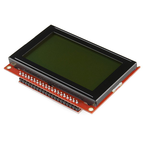
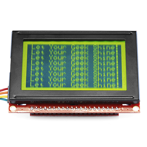
SparkFun Serial Graphic LCD 128x64
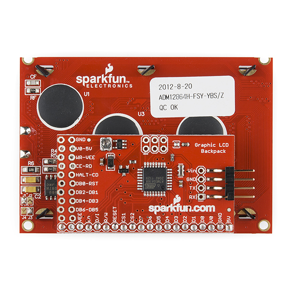
This is a smaller version of our serial graphic LCD. The SparkFun Serial Graphic LCD backpack is soldered to the 128x64 pixel Graphic LCD and provides the user a simple serial interface to a full range of controls.
Besides writing text, this serial graphic LCD allows the user to draw lines, circles and boxes, set or reset individual pixels, erase specific blocks of the display, control the backlight and adjust the baud rate. Additionally, all source code for the ATMega168 processor is compiled using the free WinAVR compiler and is free for downloading.
Check our serial graphic LCD tutorial!
- Voltage: 6V – 7V DC
- Current: 220mA (backlight at 100%)
- Input: 0-5V, 115,200bps (adjustable), 8 data bits, 1 stop bit, no parity
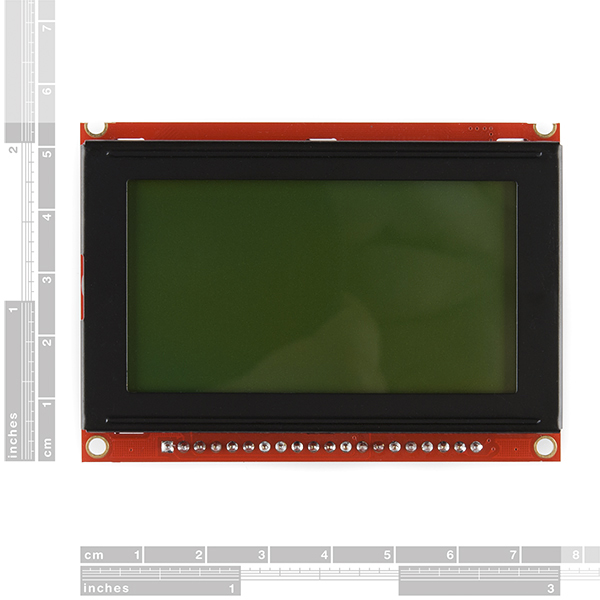
- 3 x 2 x 0.6"
- Graphic LCD Library (Pre-1.0 Compatible)
- SourceForge Page (Latest Release)
- Serial Graphic LCD Library (Post-1.0 Compatible)
- Hookup Guide
- GitHub
SparkFun Serial Graphic LCD 128x64 Product Help and Resources
Core Skill: Soldering
This skill defines how difficult the soldering is on a particular product. It might be a couple simple solder joints, or require special reflow tools.
Skill Level: Noob - Some basic soldering is required, but it is limited to a just a few pins, basic through-hole soldering, and couple (if any) polarized components. A basic soldering iron is all you should need.
See all skill levels
Core Skill: Programming
If a board needs code or communicates somehow, you're going to need to know how to program or interface with it. The programming skill is all about communication and code.
Skill Level: Rookie - You will need a better fundamental understand of what code is, and how it works. You will be using beginner-level software and development tools like Arduino. You will be dealing directly with code, but numerous examples and libraries are available. Sensors or shields will communicate with serial or TTL.
See all skill levels
Core Skill: Electrical Prototyping
If it requires power, you need to know how much, what all the pins do, and how to hook it up. You may need to reference datasheets, schematics, and know the ins and outs of electronics.
Skill Level: Competent - You will be required to reference a datasheet or schematic to know how to use a component. Your knowledge of a datasheet will only require basic features like power requirements, pinouts, or communications type. Also, you may need a power supply that?s greater than 12V or more than 1A worth of current.
See all skill levels
Comments
Looking for answers to technical questions?
We welcome your comments and suggestions below. However, if you are looking for solutions to technical questions please see our Technical Assistance page.
Customer Reviews
4 out of 5
Based on 3 ratings:
2 of 2 found this helpful:
Interchange Tx and Rx on the Hardware
We found that Tx on the board is labled on the side of real Rx, and vice versa! Other than that it works fine.
2 of 2 found this helpful:
Good display but....
The display is pretty decent. The contrast potentiometer is very sensitive so adjust in very small increments.
Actually connecting the display was just 3 wires so very easy.
Make sure to build some delays into the code as it takes a little time for the display to react. I've found a delay around 50 - 100 to be about what is needed after each write to the board.
Be careful running the example sketch. If you disconnect while the example is doing the baud changes you will have to reset the baud rate. This is documented in the hookup guide.
The library is not well documented but if you study the example that comes with the library you can figure out how to get things working.
The hookup guide is ok and gives some excellent information on the display. The ASCII commands are well documented but the hookup guide lacks depth for sending serial commands using the serial backpack. You can figure out what to do by looking at the FTDI, ASCII, and the example sketch. The hookup guide also spends a lot of time on how to reflash the firmware which was totally useless for me since I don’t have the tools to do it.
The display has issues with trying to erase lines, circles, etc without having to clear the whole screen. If you try to reset a line it simply does not work.
I wrote a very simple sketch. All it did was draw a line and try to erase the line. It wouldn't erase for anything.
As near as I can tell from the documentation and the library examples the “set” value should be 1 to draw and zero to remove or reset the pixels.
I tried about every combination of zero and 1 set values, the last value in the parenthesis, in the drawLine command and nothing worked. I tried hex values and still nothing. The line would draw every time but would not erase.
The line actually draws from a blank screen no matter what you have for the set value.
Also since this is a pixel based display it should be possible to draw letters with taller and wider fonts although no different fonts were in included in the library.
Overall a good basic display but lacks a robust library with different fonts, lacks good documentation on the serial commands, and lacks the ability to erase individual lines and circles.
Can you change the splash screen on this using the serial commands? I found an old document that says "set up the first two lines how you want them, then send..." But I was not sur eif that applied to this unit? Also, what commands, if send via arduino, will allow me to customize the splash screen?
Thanks!
I have written some alternate firmware for this display. you can get it here: http://sourceforge.net/projects/serialglcd/
some notes tho, the numbers for some of the commands are different, so you'll have to update any code that sends commands. Text acts the same, except for CR/LF are now supported. There are also some new graphics functions. they are all documented in the README. Hope this is useful.
This is fantastic code. Many thanks...works like a dream.
Guys,
I think you need to take a look at the sample source code for the serial graphic backpack. While perhaps somewhat amusing to some, I think there are some test versions of main.c in the zip file that are not appropriate for a commercial company to be distributing.
In the bigger picture, I think people probably don't need access to anything but the latest version of the code anyway.
Ideally it would be nice to put the code under source control like CVS or SVN and let users download the latest version as well as see the change log.
--- bill
I put together a collection of Arduino compatible functions to make all the drawing operations (circle, box, line) easy to perform. It includes clearing the screen and setting other serial com speeds. Simply copy and paste my drawing functions and serial.print() any strings you want to this LCD and you'll be up and running with text and graphics in minutes.
Here is a link to the drawing functions
Reading the comments in the code should be more than enough explanation!
i've also put together a library (that evernote has courteously removed line breaks for) that does larger numbers + a few letters, drawing functions, etc. if anyone wants to pick through it, the libraries and work are http://www.evernote.com/pub/iklln6/GLCdlibrarywork
. feel free to use anything you want and if you clean it up and post it anywhere that is fine too -- just give due credit :)
thanks for your works,
i have used it and complete it.
now i have a python soft that can control the LCD and print in 10x16
here is the link if somone need it:
Link
I purchased one of these displays last week for an Arduino Pro project I have been working on and it was been a dream to work with. I am using this display with the NewSoftSerial library but it only works reliably at 9600bps through software serial. With Sparkfun's datasheet it is easy to work up a small library of drawing functions to make interfacing with this LCD easier than pie. mmmm pie.
I've been using the glcd 09351 with a couple of picaxe 20x2 projects. I wonder why the default baud rate is 115,200 when most of the u-chips operate 4800 to 9600 default. Of course I can guess the display is exciting at 115,200 but in most cases this is not realistic.
Just a note to new users, the glcd is 115,200 baud and is compatible to PC serial output. Using the information in the product documents, a PC terminal program can be used to set the default to your requirements. Put a 5 second delay in your program INIT routine to allow the glcd to boot past the banner page otherwise the baud rate auto resets back to 115,200 ... Yeah pretty strange. Otherwise I find the glcd to be reliable, drawing lines and circles is no problem, even making a simple 'scope is possible and kinda fun.
Arduino Source Code for accessing the Serial Graphic LCD:
http://forum.sparkfun.com/viewtopic.php?f=8&t=20829
I can't recommend this serial graphic LCD in its current incarnation. There must be something wrong with the serial backpack software, at least when used with this 128x64 display. It is extremely flaky. If you mix graphics and text, eventually it will lose track of the text coordinates and garble the screen. If you print text past the end of the screen, it doesn't wrap back around like the documentation claims; it flickers the backlight madly. These things just shouldn't happen...
Also, the documentation has several errors:
As previously mentioned, the commands for setting X and Y coordinates are 0x18 and 0x19, respectively, NOT 0x17 and 0x18 as listed in the documentation.
Setting reverse mode (e.g. light text on dark background) is 0x12, NOT 0x18 as listed in the documentation (this should be obvious from the above).
The command for drawing a box only reads 4 parameters (x1, y1, x2, y2), not 5 as claimed in the manual. The draw/erase parameter is omitted and hard-coded as 1 (draw). If you send a 5th parameter, it will be printed as text (a blank space or so somewhere).
veAlso is there an easier way to make designs than doing this LCD.setPixel(x,y,1); for every pixel?
What would be the best way to secure it in place since the top two screw holes are cut in half?
My Application Example Code for this gLcd http://youtu.be/H_It6Hz3z8U
Not sure if anyone is paying attention to this thread anymore. I bought this product back in 2011. Finally got around to properly powering it in 2013. I loaded the summoningdark firmware and loved how well it worked. Returning to this project after a couple of weeks I clumsily hooked the backpack up to the wrong supply voltage and fried it. Thinking that the LCD could probably be salvaged I ordered a replacement standalone backpack and swapped them out. Another year later and I've finally loaded the summoningdark firmware on this new backpack and have a nicely regulated 6.38V powering the backpack.
Unfortunately, something is still very wrong. The LCD displays random lines and I've tried the reset commands and clear screen commands to no avail. Any tips on troubleshooting the LCD with the backpack on are appreciated since I would prefer not to have to order a replacement screen (having already sunk about $67 and a couple uncommitted years into this).
pero cuando le envio informacion desde arduino o desde mi mega32 usando AVR studio. todo aparece mal. pura informacion mal. entonces no se si sea algo con la configuracion de la informacion entrante. o algo del la configurqacion del chip del controlador. me pregunto si tienes acceso a los FUSES del Backpack de sparkfun para ver si son los mismos del mio y tratar de solucionarlo. estoy trabajando para arreglar este problema para q funcione. encuanto lo logre te aviso, solicito apoyo quien guste. draw code128 in c#
Please email techsupport@sparkfun and they can assist you with the issues you are having.
Please speak English! Denk je eens in hoe het er hier zou uitzien als iedereen zijn eigen taal ging spreken...
draw code 128c source .net
Why are the mounts on the top edge cut off ? How to securely mount without them ?? Sending mine back to supplier as I need to make sure I can mount it without doing some "redneck" stuff to it.
On my second one of these with no luck hooking up to any f the 4 Arduinos available to me.
Have 5v and Gnd from the Arduino and the RX pin on the display connected to the TX on the Arduino as suggested.
Libraries are in place as the demo programs etc. all compile without error. My serial 16 x 2 displays, Parallel displays and TFT displays all work fine.
What am I missing ?
If the second device is not working properly and your first screen is functional in a known good circuit that you tried with the second screen chances are the device could be bricked or defective. Please E-mail techsupport@sparkfun.com and we can take care of you.
Second one sort of works but the display is very faint even after adjusting the control for best display and ensuring I had a good supply voltage and current . Also this one has "splodges" on the screen that are always there so long as back light is on.
Who had the stupid idea of chopping off the mount holes on the top edge ? I wanted to mount this in the lid of a panel but cant really do much without a full hole.
Can send pics of the splodges. Also despite placing cursor commands just in front of the text I want to display this thing puts it in random places (pictures also available)
I emailed support already on the original issues.
Really wishing I had bought something else. I could have had larger and colour from china for less than this piece of junk. Saying that with good cause cos I will have to go through Canada Robotix RMA scheme which is designed to put you off returning things and could test anyone's patience. This display has cost me about 8 hours in time dealing with RMA and about $50 in gas. Not to mention stress.
Maybe I need to do a you tube video on how to destroy sparkfun products.
Sorry but had to vent.
UPDATE Forgot to mention this is a version 1.0. Printed on the back and does not have the sticker most of these have...noticed people mention newer versions and I only just bought this so is it possible I got "very old" stock ?
Does anyone have ideas for how to make a larger font?
Cannot get SerialGraphicLCDDemo.ino to compile (Arduino 1.0.5-r2). When it hits line:
LCD LCD;
get "'LCD' does not name a type", then a bunch of errors complaining about 'LCD' was not declared in this scope
For 2014 users:
Use "Serial Graphic LCD Library (Post-1.0 Compatible).
The pins are:
Arduino | Backpack| 5V | Vin
GND | GND
D3 | RX
Digital 3, not TX as the sample code says.. :_$
For all those having problems with this display not clearing here is a simple clear function that can be used with SoftwareSerial.h
void clearLCD(){ LCDcomm.write(0x7C); //flag LCDcomm.write((byte) 0); //clear command 0x00 = (byte) 0 delay(100);
hope this helps.
128x64 lcd here :http://www.oledlcdmodule.com/html_products/128x64-graphic-lcd-module-gray-22.html Is it compatible as this one ?
Can some one help me on how flashing the lcd to the latest source code?
Hello, I tried to change the baudrate of this serial LCD. But failed every time. The initial baudrate is 115200. So with 115200bps, I sent 0x7C 0x07 0x03 commands for 19200bps. And then changed my speed to 19200bps and sent next commands. But gabage on the screen. Altenately with 115200bps, I sent 0x7C 0x07 0x33 commands for 19200bps. And then changed my speed to 19200bps and sent next commands. Same gabage. It means the baudrate was not changed. I was wrong? What is the truth?
I am trying to put a clock to the display. I use gotoPosition to write it in the same place. Sometimes it writes somewhere else or it writes my information incomplete?
What can i do? Would changing the baud rate to some smaller value would help?
Hello,
I created a serial interface for 128x64 graphic LCD, this reduces the pin requirement from 14 to just 2. Check it out: -
https://sites.google.com/site/hobbydebraj/home/2-line-interface-for-graphic-lcd
I'm a newby and didn't know where to start. Thanks to Tahaic's post above( https://www.sparkfun.com/products/9351#comment-4eaad851757b7fd351008a9f )I was able to pull it all together. One slight issue that I had at the end, was getting two avrdude errors - can't open device "giveio" and failed to open parallel port "lpt1". I was able to fix that by executing the install_giveio.bat, and now it runs great. Thanks Tahaic
Hello, thank you in advance for your help, I am using this display connected to the serial output of a device based on Cinterion XT65, when I try to send control sequences to clear the screen or running the demo, shows strange characters instead of running commands (see picture in http://www.flickr.com/photos/g_riveras/6992596295/). I am using the following routine Java ME:
//------------------------------------------------------------------ protected void startApp() throws MIDletStateChangeException {
// Limpia pantalla buffer0[0] = 0x7C;
buffer0[1] = 0x00;
com_os0.write(buffer0);
// Ejecuta demo de funcionamiento buffer0[0] = 0x7C;
buffer0[1] = 0x04;
com_os0.write(buffer0);
//------------------------------------------------------------------
Thanks.
Is there any demo code for PIC18f4620 so that i can check whether my LCD is working or not? All I have been seeing is for ATmel controller.Any help regarding the PIC to start testing my LCD would be great. Thanks
Is there any Graphical LCD library for PIC18f4620 microcontroller. I have adapted the given library but it does not seem working?
I just bought an LCD screen like this and the demo doesn't work at all with Arduino 1.0. Can Sparkfun team update it;s library and demo for Arduino 1.0? Thank you.
I just bought an LCD screen like this and the demo doesn't work at all with Arduino 1.0. Can Sparkfun team update it;s library and demo for Arduino 1.0? Thank you.
Comment from our customer Frederick:
"This has been a Great display, However the Default Baud Rate (115,200bps) is a real hassel.
I use this display on my PIC projects and to use it causes problems.
To keep my experiments at minimal I do not use the PIC UART and typically 9,600 bps is used.
I can set it correctley and use power up delays etc and I use my PC Com Port to reset it from 115,200bps to 9,600bps.
It just would be a lot more useful and sensible if it defaulted to 9,000bps so I can change it to something higher using my PIC's and not rely on the PC.."
Hello Tonik, DO you have graphical LCD library for the PIC microcontroller? I have been trying to get something on my LCD but nothing is displaying. I am using PIC18f4620 microcontroller.
Thanks
are these really anny good?
Hi guys im quite new to all this and am trying to run a serial graphic lcd with my arduino duemilanove. Apparently i have to flash my lcd but im unsure how to do so. I have an AVRISP MKII that im supposedly suppose to use. Any ideas to get me started?
I have a problem getting the LCD to work.
When I send commands, the display prints the characters on the screen but nothing happens, for example - I want to run the demo, so I've sent 0x7C 0x04,and the display just showed it on screen without doing anything else.
Can anyone suggest a solution?
I have purchased one and I feel lost. I only give strange characters in the LCD. I have read a little to try to understand why this lcd dont work properly. I'm not very sure but I think I have to install a new firmware but I dont know how.
Please help me, thanks :)
Is there anything I can do to determine if the firmware is new or if it is the old firmware I read complaints about.
I can draw boxes and send text Ok, is it possible to rotate the characters 90 degrees and make double size characters?
The baud rate reset to 115200 is not a problem if the program begins with a long delay (5 seconds here) before sending a serial stream. Once the display resets to 115200 its necessary to use a PC terminal emulator at 115200 to send the control string for lower baud rates. So far this has not been a problem.
picaxe 20X2 user at 9600 baud.
fixed polarity problem
This looks like a VERY nice. I am PROBABLY going to get one as soon as I figure out EXACTLY how to use it with my Picaxe. P.s., I am making a Picaxe based "laptop" with parts from sparkfun. If possible, all from here. Because i love sparkfun but thats not related lol.
Why aren't these stocked in different colors? Adafruit has them.
White on Black
White on Blue
I'm sure there are differences, but there grey/green one is a lot cheaper, too.
"Serial interface uses only 4 or 5 digital pins"
The product on this page only uses one pin.
I'm confused. The Graphic LCD Library that is linked to in the product description on this page is ONLY for use with the firmware written by SummoningDark. However, the Source Code that is linked to in the same place appears to be the 05/11/10 firmware version that (by what I glean from the comments) is somewhat improved from the original, yet still unacceptably buggy.
Did Sparkfun finally do the right thing, and incorporate the improved firmware? Or are they still shipping this product with the known problematic firmware, and further confusing the issue by linking to a library with incompatible functions?
Before I proceed with plans to use this display in an upcoming project, I need to know if I should purchase a programmer, and begin climbing the learning curve to reflashing the chip.
Don't get me wrong... I need to learn how to do this eventually, but this project already has me facing several learning hurdles, within a tight time frame. I need to choose my hurdles wisely ;)
Thanks in advance!
The firmware thats on the product when you purchase it is NOT SummoningDark's. The library i wrote for it (the one linked above) only works if you flash it with SummoningDark's firmware.
I could write a library for the original firmware, but i'm waiting for a new ISP cable, so i cant test it right now. However, i think it should work with just a few minor modifications if you can live with the bugs...
just making sure before i buy this. this is one thing that comes with the glcd and the backpack?
Yes, but be aware of the bugs in the original firmware. Read here http://forum.sparkfun.com/viewtopic.php?f=8&t=28317
I have written a library for the firmware made by SummoningDark
Read the forum post HERE
This firmware and library will make the product work as it should, with NO BUGS!
Hi sparkfun, new problem on the screen here.... I'm using 115200 baud, i have a routine that updates a temperature reading every 5 seconds, I clear a box where the previous temp was and update the newer temp. But I have a black box that shows up to the right of my written text.....what is causing this? I set the baud to 9600 and ran the routine, same thing :(
Here's a link to a pic of the blocks i was talking about...
http://i6.photobucket.com/albums/y205/andrewnriley/302.jpg
I started troubleshooting the problem. The black box printed on the screen is a '0x00'. So i looked into what would be causing that, I had an older function to Erase a block from an arduino library that i used to reference for my pic library i made. It was passing in 5 parameters, the 5th one being 0 or 1,which thanks to @PhysComp Hobbyist, I read his comment a from a while back saying that the 5th parameter is not supposed to be there, so I updated the library i setup and the blocks are gone.
My display has been working fine, until i disconnected it from my arduino (to try out my new cellular module :). Now if i connect my LCD and arduino and try to upload I always get this error:
avrdude: stk500_recv(): programmer is not responding
avrdude: stk500_disable(): protocol error, expect=0x14, resp=0x51
I can upload if I disconnect the LCD (tx/rx). But when I connect it again I get blank screen using my previous working code.
Does anyone know how to solve this?
Hey sparkfun, I was wondering if there is any timing requirements between the (0x7c) command and any write after words? (Ex: Running the demo code: WriteUART1(0x7c); WriteUART1(0x04);)... I have a PIC32 i'm using the glcd with, and i'm referencing the arduino example code to make up my own code for the pic, just wanted to know if I should have any sort of delay statemnt inbetween these writes. thanks!
Hi again, you know, no delay needed i found out. I wasn't getting anything on the display, and i came to find out that the pot on the back of the screen is very sensitive! I barely turned it and got the demo command showing. cheers.
I purchased one of the 128x64 displays along with the serial backpack to be included on my robot which is operated by the Orangutan SVP MCU by Pololu. I am the most extreme novice when it comes to coding. My question is, what all functions must I include in my code if I simply wish for my screen to display 4 digits, each of which is 1" tall?
That is basically what I am trying to do. For me I'm scaling an analog signal to a digital range and displaying that on the screen. I came up with my own code to display these numbers using full character blocks but I am currently looking at SummoningDark's code (see link above) but I need to convert my own sprites. If I figure it out I'll let you know.
I ordered one of these for a project at work. I'm using the arduino platform and have done a few simple work-around projects with them here at work.
When writing text to this, how hard is it to change the sizing? I'm wanting a big 4 digit number display with some smaller text below it. Will I have to create the numbers individually with draw functions? Or is there code to make the font larger?
You can try my firmware. It has support for two fonts, and you can switch back and forth with a simple command. By default, one is the original 5x8 and one is a double size 10x16, but utilities are included to make your own fonts if you choose. http://serialglcd.sourceforge.net/
I downloaded it but I'm not exactly sure how to update this firmware. Just guessing but I bet I don't have the programmer required for this device.
you need something that can program AVR's. I use a BusPirate, but there are many options. googling avr programmer should bring up plenty of hits. There are six unpopulated pads on the board over the microcontroller, they are the programming pins. I forget the layout but i'm pretty sure is it a standard pattern that sparkfun uses. There is a tutorial on programming avr's here http://www.sparkfun.com/tutorials/93
hopefully this will get you going.
I bought my first Aurduino (UNO Eleven) with this LCD and backpack 2 days ago. I got the backpack on the LCD with the idea it would simplify the interface to the LCD. I quickly came to the realisation that the rendering of this display was very slow and there was no flow control (e.g. Xon, Xoff) which ment I was going to run into trouble real quick with having to put delays in my code. Looking around I found SummoningDark's firmware at http://serialglcd.sourceforge.net/ and I wanted to try it but didn't know how to get the main.hex into the ATmega168. I finally worked it out and this is what I did:
I built a simple programmer cable like this except I used 100ohm resistors - just used stuff I had laying around. I connected the cable to the 6 pin ISP connection on the backpack as shown here which is explained about a 1/3 of the way down on the page. I confirmed these connections with the pinouts from the manufactures datasheets which is on page 2 here . I downloaded and installed WinAVR from here . I changed the programmer options in SummoningDark's firmware makefile (in firmware\trunk folder) to direct parallel "dapa" which has the correct pin out for this programmer cable (i.e AVRDUDE__PROGRAMMER = dapa)and also changed the port to lpt1 (i.e. AVRDUDE_PORT = lpt1). I'll just mention here that programmer types are defined in the avrdude.conf file in WinAVR\bin folder. I then opened command prompt and changed directory to firmware\trunk folder and typed "make all" to recompile the main.hex file (WinAVR install adds its path to the system path variable so windows knows where make and avrdude is).
With the LCD powered by the +5V from my Arduino (Arduino plugged into the USB) and the programmer cable connected to computers LPT1 I typed "make program" at the command prompt and avrdude proceded to flash the ATmega168 on the backpack. It said "verification error" and "safemode lfuse changed! Would you like this fuse to be changed back? y/n" I typed "n" and pressed enter...it did the same for hfuse and efuse and I said no to all three. I then flashed it again to check and it said fuses OK avrdude DONE. Thank You.
My backpack works fine now! Thanks to SummoningDark's firmware .... awesome job! I would like to try and contribute to this firmware - I have a few ideas. I hope this helps someone.... as it took me the last 2 days to figure all this stuff out.
For those of you trying to re-flash the 128x64 LCD like myself, I used TAHAIC's post to figure out which pins on the LCD backpack were which. I wish I could post pictures because I made a great diagram for myself that would save you a lot of trouble, but I can't. So....
The most time consuming part was finding the correct pins on the sparkfun backpack. Here are some additions to the post above that might help. On my backpack the AtmegaGA168 is a square shapped micro-controller but is mounted upside down. Using a flashlight I read the label on the chip that said "AtMegaGA169". The black circle on this chip marks pin 1. For the following tips to work place pin 1 so it's the top left cornor this might mean you have to rotate the PCB upsidedown. The bottom right pin, when pin 1 is top left, is the MISO pin. When pin 1 is the top left pin, just below the mirco controller there are 6 holes in the PCB board these are the programmer holes. You need to find hole 1. Hole 1 is tied directly to the MISO pin on the microcontroller, the Atmega168. I just used continuity on my multimeter to varify. I put one lead from my multimeter in the programmer holes on the backpack pcb and the other on pin16 on the micro controller. I got continuity!
What was hard for me anyways, was that 1.) the microcontroller is upside down. 2.) the programmer pins are backwards, when the PCB is upsidedown pin 1 is top right, when you'd expect it to be top left. 3.) I am kinda new at this.
Finally, I'm sorry if I was too wordy. I tried really hard to use clear steps. Also... didn't use spell check...
Oh and forget doing this if you have windows vista/7 especially 64 bit....
Hi,
I have an avr isp mk2 and avr studio 5, I am a total newb also. What do I need to do to flash the firmware? What needs changing in the make file?
Cheers,
andy
Thanks, I received my BusPirate and cable today. I will take a look at the tutorial you suggested. Looking to use your firmware - need to setup 10 bigger sprites (0-9). Currently I coded a work around using 5 lines, 3 positions, and an invalid character that displays a filled block to make bigger numbers. It is a bunch of code that I could do without.
how large do you need your numbers? I could whip up another font header which you could substitute for the 10x16 one in the current firmware.
So, I've been having THE most difficult time getting this to work with an Arduino Pro 328 (the same referenced in the NCWP under tutorial). The culprit seems to be the NewSoftwareSerial library.
After recommendation of the good people at the SparkFun IRC, this LCD works under the following setup:
* Mac OS X 10.6
* Arudino 022
* Tools->Board->Arduino Duemilanove or Nano w/ ATMega328
* Arduino Pro 328
* LCD RX -> TX(1) on Arduino
the following sketch works;
void setup()
{
Serial.begin(115200);
}
void loop()
{
clearScreen();
delay(1000);
Serial.print("HI!");
delay(5000);
}
void clearScreen()
{
Serial.print(0x7C,BYTE);
Serial.print(0x00,BYTE);
}
maybe the author of NCWP can shed some light into why NSS doesn't seem to work correctly?
Hey E.Mk,
I am attempting to run your code with my Pololu Orangutan SVP-1284 MCU. I am coding in the AVR environment so I obviously had to make minor adjustments to your code, though I am still getting errors. I admit that I am the most extreme novice when it comes to coding, but my main goal is to get my GLCD to display 4 digits, each of which 1" tall. Any suggestions would be greatly appreciated.
Thank you and have a great day.
I used newsoftserial just fine. you should be able to use NSS with this, I have another project I just started working on yesterday that uses this same screen, and it works just fine. Are your rx/tx pins messed up? what's not working for you?
Hey RobertC,
I used a stripped down version of the source code from NCWP, as well as a few tutorials I found on the forums() - the problem seems to be that the digital pins are noisy or something. As soon as the Arduino starts up, the LCD goes nuts(bars/weird gibberish fill the screen)
I used the LCD+wires on a different MCU and that worked fine.
Also tried using Arduino Pro Mini 328 - got the same result. Since using the hardware TX pin works, I am thinking that this is either a NSS issue or I didn't set up the library correctly?
Which version of NSS are you using? I used the latest from the arduiniana site (http://arduiniana.org/NewSoftSerial/NewSoftSerial10c.zip)
I heard from someone from the SparkFun IRC that NSS is wonky and apparently not reliable?
Thanks,
E.Mk
P.S. - BTW, excellent NCWP tutorial!!
I used the most recent at the time. It was probably similar. I've used it for many applications since then and it's always been very reliable. Yes, you will get noise coming across the lines when uploading code, this is normal. However, once code is up there, you can just unplug everything, then boot the system up with power (not USB) and it should be fine.
The library doesn't really need to be 'set up'. You just define the tx and rx pins, and then the baud rate, and you're good.
Thanks to RobertC. we were able to deduce the problem - apparently there was something wrong with the NSS installation on my set up.
I re-installed NSS library and now everything works!
The following sample sketch WORKS on my Arduino Pro 328 + LCD
**(substitute [] with the less than and greater than symbols)
#include [NewSoftSerial.h]
NewSoftSerial LCD(2,3);
void setup()
{
LCD.begin(115200);
}
void loop()
{
LCD.print("test");
delay(2000);
}
Thanks again, Robert!
how do i update the firmware? sorry if im just a noob but im trying to get this to work. I open the makefile in textpad but not really sure what to do with it. what hardware do i need?
Thanks
Hello,
i have LCD-09351 with serial backpak on it, but i have a problem.
When i power up the displey there
s no logo, and the picture is this:
[picture](http://a5.sphotos.ak.fbcdn.net/hphotos-ak-ash1/hs886.ash1/179495_1840544413071_1224363156_2220755_1008597_n.jpg)
Can some one help? It
s broken?Hy,
I am having the same problem! Some explanation? Some fix? Thanks in advance.
I had a lot of problems when I first bought this, but I finally got a working backpack thanks to SummoningDark's firmware.
I would suggest anyone that buys this to load the firmware instead of spending hours hitting your head against the wall.
Here is the link
http://serialglcd.sourceforge.net/
It fixes the issues with slowness, flipped Y axis, the erase function not working and others.
I hope that Sparkfun can adopt this as the official firmware.
not sure if this is any similar to the older version of the lcd, but I have simple text driver for PIC.
get the source code from
http://joekwuen.blogspot.com/2011/01/project-pic-lcd-module.html
I have been examining some strange behaviour I am seeing with these devices such as unintentional dimming of the backlight, strange characters displayed, and tripping of the reset circuit.
I tracked the problem down to a sudden jump in current consumption from 20mA to 200mA (backlight off, 7V supply) when writing chars to the last row of the display. The current consumption remains at 20mA when writing X's to the LCD, until I reach the last row.. Software bug?
Overall I am impressed with price and how easy these serial LCDs are to work with. I figure a software modification might fix this? (These LCDs came with software edited on 5/11/10)
This display would be a LOT better if the refresh rate was not so low. Perhaps Sparkfun could use a better/ faster microcontroller in a future upgrade? Overall, it is not to bad of a device..
For the moment, I'd like to send command strings to this from a PC. I've configured a serial port for 115,200 baud, 8N1. Something is clearly getting through, as the display adds a "character" for each keystroke. The character that gets displayed has no obvious correlation with the character I send, though. I can think of a number of things that could cause problems: voltage levels, slew rate (given test clip connectivity), subtle timing errors. Has anyone had any luck doing this?
Are you sure you aren't sending a 'carriage return' or 'enter' or something after each character?
Voltage levels. I kludged up the "normal" one-transistor level converter to take the PC's TX at RS232 levels to the backpack's RX at TTL levels out of parts I had at hand and it seems to work okay. Other than some of the complaints made above about slow response, etc.
I think I voided my warranty, though it wouldn't surprise me to hear SFE pledge to still support it (I think they like you to do stuff like this :) )...
I soldered a 4 wire ribbon cable directly to the back and then laid it face down on a piece of wax paper. I covered the back with a few pieces of fiberglass tape slathered in epoxy. Let it dry, flipped it over and filled the cavities and covered the screen with epoxy. It will have a piece of UV resistant Lexan between it and sunlight. Anyway, it still works fine even when totally submerged in water.
Previous caveats by others still apply - if you throw more than lightweight graphics at it, it may have issues. It can reset to 115k pretty easily (in my startup code, I set it back to 115k every time and then set my baud rate). But for a simple text screen that can handle a few dials or other simple graphics, it is hard to beat at this price. Knowing it can be "ruggedized" makes it an even better deal.
Concerning the baud rate - why default to such a high speed when the device writes so slowly? The screen write speed is fine for my purposes, but the default baud rate that is easily reset is an issue. I have mine sharing a serial port with a GPS. It would really be nice if I could disable the reset to 115k. The unit is a lot more dependable at 4800 anyway.
I've been moderately pleased with this device.
I mostly got this for it's text abilities; it has a lot more space than most text only LCDs have.
However, I wanted to see what else I could do, so I tried doing some (simple) animations. The 416 byte buffer on-board makes this a headache. Because the TX line is unused on this unit, there is no flow control at all, which means you have to guess the rate of drawing on the device and slow down the transmission of the commands accordingly in the (client) software.
Here's my Python code that I wrote to control this device, it includes the appropriate client side buffering you need if you're planning on doing any animation:
https://github.com/EnigmaCurry/Sparkfun-LCD
If you are doing animations, The firmware I wrote for this device might help you. it has a sprite functionality that would let you place small images on the screen with a short command(6 bytes). that way you could quickly change the graphics while sending minimal data. the default code is compiled for 8 16x16 sprites, but that can be changed if you re-compile it.
Just got one of these 'working' with an Arduino board today, just bought from SparkFun last week. Here's what I found:
1. They're not kidding about the voltage requirement being 6 or 7 VDC, Running this on 5V seems to result in significant backlight and contrast variations.
2. The box function claims to take 5 parameters, two x/y coordinates and a byte to indicate black or clear pixels according to the datasheet; however in reality the function only takes 4 parameters; the fifth one is sent to the screen as text output. (Verified in driver source code)
3. Although the line function does take 5 parameters (2 pairs of x/y and a set or clear byte), it appears to not correctly interpret the clear command; I seem to be unable to 'clear' a line of pixels using the line command
4. It turned out to be very easy to overrun the controller with data; liberal application of delay() was required to keep everything moving
Needing just 1 output pin to address the display is a major plus, dealing with the firmware issues on the backpack is a pain.
Niels.
Hey I was wondering if someone could answer a question about this LCD for me.
I'm wanting to run this with an arduino duemenovo thingy with an Atmega328 and want to know if there's a library I could download from somewhere and anything else I'd need to run this. Thanks heaps
I am trying to use this with a Picaxe 28x1, but I can't get it to display anything but black boxes witch are blinking. I'm new to microcontrollers and Lcd's and it is very confusing to match together all the required information on how to get it work.
I run my Picaxe at 4Mhz. What baud rate and
polarity of the signal should I use? (do I need to make some kind of circuit to switch the serial signal???)
Default baud rate is 115,200kbps. It sounds like a baud rate issue. If you have any other technical questions, please direct them to techsupport@sparkfun.com. Thanks.
Thank you! It is working now.
(Continued from above, due to character limit)
3.) I noticed that nobody on here mentioned how long to wait after the LCD powers on to start sending data. I looked at the code for the board and figured out that its roughly 2554ms (according to code) before it enters its while loop and starts getting input. However if you don't send data within (estimate) 10-20ms of power on, it will show the baud rate. I waited 1000ms, and that worked for me. Keep in mind that it will vary for you - it takes time for your controller to start up and so forth before it gets to the point where it'll start "waiting" for the display to be ready as well.
I'll post if I have anything else to share.
Wanted to update the information I provided because its wrong. I realized that if you put any data into the LCD before it enters the while() loop, it will default to 115200 and show that. The only way to avoid that is to wait 1.5sec (for me).
Just wanted to leave some tidbits about this.
1.) I'm using 5V for my entire circuit. I saw that the 6V pin goes to a voltage regulator. Solution? Instead of connecting the VDD on the 4 pin header to 6v, I connected the 5V hole on the other side of the board (left side) directly to 5v supply. Now it works fine without needing 6v. This bypasses the regulator, but if you want to be safe - could permanently disable it.
2.) A bug: When you draw a box and you draw it near the edge of the LCD, it could go into an internal loop. I'm not quite sure why it does this, but try drawing a box from 0,0 to 20,20 or so. You'll notice that everything on the display will get more faint, like its continuously refreshing the display - even though I'm drawing it once. I got around this by using lines instead, but I noticed that its very sensitive about certain elements near its boundaries - i.e. X=0, Y=0, or X=128 Y=64 or any combination. I'll be happy to try and replicate this bug, but wanted to tell anybody that has the issue - just use lines. Or move your box away from the boundary.
Guys, I am trying to interface this LCD with an MSP430 uP. But the MSP works at 3.3V how can i connect this two.
Thank You,
J
Use a logic level converter:
http://www.sparkfun.com/commerce/product_info.php?products_id=8745
I'm using mine with a 3.3v microchip dspic, and it works fine. just make sure your micro pins are 5v tolerant if you want to do communication from the LCD back to the micro. If necessary you could make a voltage clamping circuit with a 3.3v zener and a resistor.
Hey guys I would like to use this LCD with an MSP430 microcontroller which runs at 3.3V. Can this be done?
Thank You
J
I've upgraded my unit to the new Sparkfun firmware, but it appears that two vertical bands in the LCD display are not getting addressed. Has anyone else seen this?
I'm running the demo code and when it prints out the alphabet, characters are split where the unit seems to skip past the "dead" bands. Characters aren't missing, they are split across the non-functional areas. Here's a picture.
http://2.bp.blogspot.com/_Eogk12oYm-g/TGtYLjvkn4I/AAAAAAAAAL4/KDWDIjL85S4/s1600/SerialGraphicLCDProblem2.jpg
I may be missing something, but I've read this thread a number of times and I don't see where to get the new Sparkfun firmware. I thought all my problems were that the display was bad, but after reading the notes about needing additional voltage (over the 5v arduino or usb leads I've been using) and the firmware, I'm optimistic I might actually be able to use this. Can someone point me to where to get the new SFE firmware?
Hi,
I bought it recently, and noticed that the on-board regulator is getting pretty hot even at 6V input. I searched for the data sheet of the regulator and I was surprised to see that the regulator is 150mA, but the LCD on max brightness uses more than 200mA. I haven't measured the exact temperature, but I can't hold my finger when its hot, so I guess its not very healthy for the regulator. At 50% brightness, the current is exactly 150 mA and the regulator is only warm, so I guess that would be the max brightness I am gonna use.
I also want to ask is it possible to program the on board atmega 168 without removing the chip? If yes, then what kind of connection, programmer etc to use?
Thanks in advance
i got this LCD back in january, and i have to admit i was pretty unsatisfied. i've even been considering desoldering the backpack and just running it with the digital I/O's. well i just flashed the update and i let me be the first to say GREAT job! i'd spent so many hours fidgeting with delays to try to get things to display properly without erroneous lines and miscommunications, which never really succeeded, but now the screen catches all the sent bytes with 625?s delays and actually draws to the screen without me watching the line move pixel by pixel. i might buy another one now(!)
to those who haven't flashed their old LCD's yet, just read the Makefile and follow the instructions down to 'make program'...if you're on a mac you should know by now to go down and remove the AVRDUDE_PORT entries. it's just programming an ATMega168; don't be scared, it's worth it
Great advice! The new code is a lot better.
I flashed the new code last night, and it seems a little better, but I'm still surprised at how slow the unit is at rendering text. I can literally see it printing out the text, character by character. It can do maybe 2-3 lines per second. Is this what everyone else is seeing?
In contrast, my 20x4 line displays can render the entire LCD in probably a tenth of a second ( you can barely see it ). This is my first foray into graphic LCD's, and if this is normal then set me straight. ;)
Thanks,
Nathan
MrRoot.net
Hey, this unit seems to be extremely liberal with the "any character received at 115200 baud during the splash screen resets it to 115200".
My LCD repeatably resets to 115200 under totally awesome circumstances which is relaxing and not annoying at all! Super fun unit!
Yes, that is liberal. You can disable the splash screen though.
I've been having trouble with the Screen resetting when I try to move objects that I've drawn on the screen. It will reset after a couple of seconds some times sooner. I'm using the serial com of an HCS12 @ 38400 baud and the backpack vcc is at ~7V. Everything is has a common ground too. I've also tried varying delays before sending the commands too redraw the screen and turning off the back light.
I am running into performance issues with the 124x64 serial LCD.
The LCD responds slowly! Even when only drawing a single line accost the screen, one can see the line start at the left and proceed slowly across to the other side. I would say it takes about 100 ms to draw.
I am running the pack at 9V with a very low backlight setting. And its plugged directly into my Arduino TX/RX.
Can someone tell me if this is the expected performance? I was hoping to get the same performance that I saw in the UV demo for the 160x128 serial LCD.
Thank you,
Peter
I've been playing with this for a while and am starting to think there might be a problem with the backpack. I seem to get a an endless stream of random characters and symbols showing up on the screen. Also the potentiometer is very sensitive i.e. if I tap it I wont be able to see any of the streaming randomness.
So far I havnt been able to get it to do anything by sending the commands ('|' (command)). I've tried with the serial coms on my HCS12 microDragon, and my Boarduino boards.
Does this sound like I have a bad backpack?
Its just picking up noise. switch to a lower baud and make sure that your uC and LCD share a common ground. Worked for me.
For the folks that are having troubles with the flickering, this is a very simple explanation. The data sheet says very plainly that the unit operates from between 6-7 vdc. The Arduino only supplies 5 vdc if you are using the regulated voltage. Therefore the display is probably being starved for power. I added a dedicated 7 volt regulator and those problems went away.
If you are using the serial pack at 115200 baud then you better be sure to have very good wiring between the Arduino and the display. At that baud rate the bit times get very short and if there is any interference or line capacitance then the rise/fall times are going to be all wrong. Try slowing it down some and see if the problems go away.
Russ
While this was definitely easy to setup and get text printed, I have to agree with comments already posted and that I am VERY disappointed.
It's a nice big screen, but the back light blinks during writes, and the contrast fades as you write data to it.
Additionally, if I draw circles too fast or or mix commands or look at it cross eyed, it resets and prints garbage.
Unless I'm printing text to it or setting one pixel at a time, this is VERY unstable.
Very disappointed.
Another warning - the firmware contains some serious bugs which makes the display almost completely unusable (unless you are just sending characters and no commands, e.g. set location etc)
I've had a look at the code and identified a handful of bugs, I have to order the programmer so that I can test it...
After struggling for hours trying to figure out why nothing would show up on the display. I found the problem to be a non-connected pad on the potentiometer on the back. It wasn't broken off but not even soldered at all...
Found another issue: When I write a lot of data, the contrast goes all the way down (lighter).
Hmmm....
I am having an issue with the text not being written to the correct coords. On certain coords, the text will mostly write correctly, but will sometimes write to the side or below the coords.
The backlight also blinks during writing.
Will there be any FW upgrades for this unit?
Discovered an important problem. The datasheet says use 0x17 and 0x18 for setting X and Y position. That is wrong. I had to look at the source code (thank you for providing it) and it is actually 0x18 for X and 0x19 for Y.
For confirmation check main.c line 527. It looks for 24 (hex 0x18) and 25 (hex 0x19). The Datasheet says to use 0x17 and 0x18 on page 3.
Also it should be pointed out that 0,0 is the bottom left corner. X counts from the left but Y counts from the bottom. 0,63 is the upper left hand corner. Not a big deal but it's useful info.
Thank you for providing the source code!
Just got two of these in today. Very easy to setup and use with an arduino. I highly recommend these for someone who wants a b/w graphical LCD without any hassles. Just provide pwr, gnd, and connect the arduino RX to the LCD TX and vice versa.
Example sketch:
void setup()
{
Serial.begin(115200);
//Change backlight value
Serial.print(0x7C,BYTE); // cmd
Serial.print(0x02,BYTE); // brightness
Serial.print(0x40,BYTE); // value between 0-100
//Run the built in demo
Serial.print(0x7C,BYTE); // cmd
Serial.print(0x04,BYTE); // demo
}
void loop() {}
Does come in red backlight?
I guess I could just through in a red gel on it, but it would be nice for my project to have it in black background and red graphics.
Otherwise, I ll have to stick with the 2x16 panel.
When do you expect to have it on your inventory?
I'm not a programmer I just tinker with Arduino so I'm just documenting what I got to work and what I couldn't get to work.
The hookup guide spends more time explaining how to change firmware than anything else. The hookup guide is somewhat useful but it's pretty much what it says a hookup guide. Use the demo code to figure out how to write your program.
I used the library supplied by Sparkfun along with the softwareserial library on an Arduino Mega 2560 and an Arduino Uno.
For me the vu meter example didn't do anything for me as I could never figure out the code. Far more code for the vu meter than I needed just to figure out how to get this display to work. For an advanced programmer it would probably have helped but for a less than novice programmer it was no help. A more simple example would be preferred.
Display works but you have to give it time to work so add delays in after every command to the display. 1 - 2 seconds seems to be about right for most commands. I tried different baud rates and all seem to work but all need delays after sending the commands to the display.
I was not able to verify the setHome() function works but it doesn't seem necessary as you can send the curser anywhere you want with setx() and sety().
I never could get clearScreen() to work correctly but I used eraseBlock(0,0,128,64). Give it a 2 - 3 second delay after the command to get the screen cleared. It was odd that the demo program used clearScreen() extensively and it worked but I wasn't able to get it to work with any code I wrote. Likely a programming issue on my side and no fault of the display or firmware.
After uploading new code to the Arduino I found some strange things happening on the LCD. After I uploaded the code I would give it a chance to run and it usually seemed like it wouldn't work or would write charectors in the wrong place. Then I started manually resetting the Arduino with the reset button on the board after an upload of new code and the display would reflect the new version that was uploaded.
Also ran into something with the serial buffer that it wouldn't print the last character you send it. Then when you send it the next string it would start with the last character of the previous string and drop the last character of the string you just sent it. I saw mention of this somewhere in some documentation that I found during a search but I couldn't find it again once I realized what was happening. This lead to clearing the serial buffer in the setup routine of my program before the display needs to do anything.
Don't forget to initialize an instance of softwareserial with the correct pins and setup the baud for softwareserial in the setup portion of your sketch.
The only way I was able to send decimal numbers to this display was to send the integer part of the number (left of the decimal) with printNum() then take the decimal part of the number and change it to an integer and round it to the decimal precision you are looking for and use printNum() to send it to a different place on the screen past the decimal. Print the number in 2 parts using printNum() to two different places on the screen so it looks like a number with a decimal but is actually two integers separated by a decimal. There is probably a better way to do this I just didn't figure it out.
Overall the display seems to work it's just very slow so if your project can tolerate slowing down the loop with delays to print to the LCD display you are good to go.
how do i update the firmware? sorry if im just a noob but im trying to get this to work. what hardware do i need? Please help me. Thanks