- Home
- Product Categories
- Monochrome
- Graphic LCD 128x64 STN LED Backlight

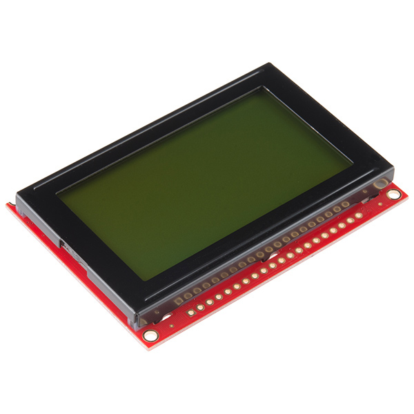
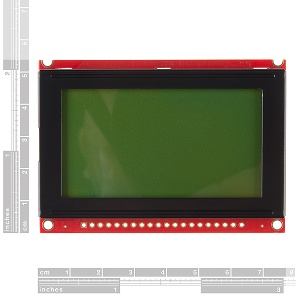
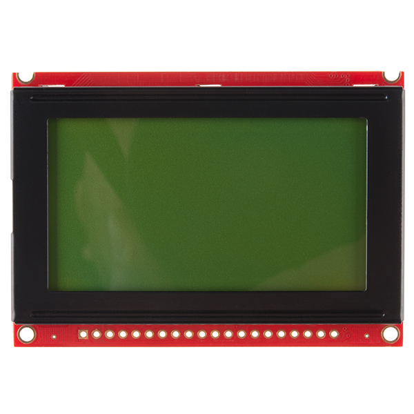
Graphic LCD 128x64 STN LED Backlight
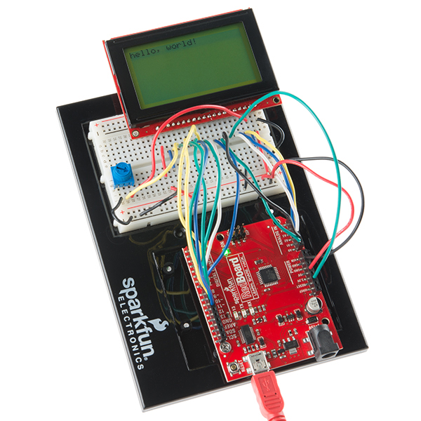
This is a framed graphical LCD 64x128 with LED backlight. This unit is a very clear STN type LCD with a simple command interface. This new module includes the negative voltage circuitry on board!
Utilizes the extremely common KS0108B parallel interface chipset (datasheet). Interface code is freely available. Includes LED Backlight.
- Overall: 75x52.7mm
- Viewable area: 55.01x27.49mm
Graphic LCD 128x64 STN LED Backlight Product Help and Resources
1 of 1 found this helpful:
Enclosure Designs
If you need to make an enclosure out of acrylic, check out the vector files from this tutorial by Nathan Chantrell => http://nathan.chantrell.net/20111015/building-a-graphical-display-for-openenergymonitor/.
Core Skill: Soldering
This skill defines how difficult the soldering is on a particular product. It might be a couple simple solder joints, or require special reflow tools.
Skill Level: Noob - Some basic soldering is required, but it is limited to a just a few pins, basic through-hole soldering, and couple (if any) polarized components. A basic soldering iron is all you should need.
See all skill levels
Core Skill: Programming
If a board needs code or communicates somehow, you're going to need to know how to program or interface with it. The programming skill is all about communication and code.
Skill Level: Rookie - You will need a better fundamental understand of what code is, and how it works. You will be using beginner-level software and development tools like Arduino. You will be dealing directly with code, but numerous examples and libraries are available. Sensors or shields will communicate with serial or TTL.
See all skill levels
Core Skill: Electrical Prototyping
If it requires power, you need to know how much, what all the pins do, and how to hook it up. You may need to reference datasheets, schematics, and know the ins and outs of electronics.
Skill Level: Competent - You will be required to reference a datasheet or schematic to know how to use a component. Your knowledge of a datasheet will only require basic features like power requirements, pinouts, or communications type. Also, you may need a power supply that?s greater than 12V or more than 1A worth of current.
See all skill levels
Comments
Looking for answers to technical questions?
We welcome your comments and suggestions below. However, if you are looking for solutions to technical questions please see our Technical Assistance page.
Customer Reviews
4.4 out of 5
Based on 7 ratings:
2 of 2 found this helpful:
Great display, mediocre documentation.
Bought this as a replacement display in a Unitronics industrial PLC/HMI
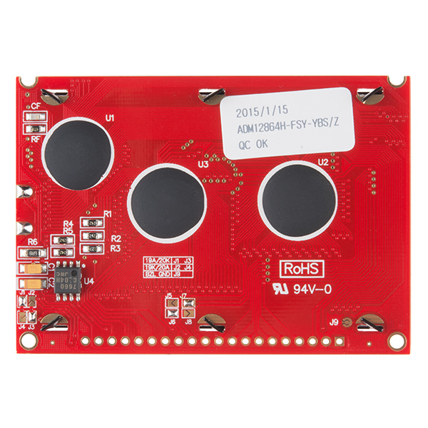
When I powered up the PLC with the new display, the left half was on the right side of the display, and the right half was on the left side. I had suspicions that it was a chip select issue, as the display has two drivers for the vertical lines. I had noticed some solder-jumpers on the board, but I found no info about the jumpers in any datasheet. After some measuring I removed the solder from J6 and J7, and added solder to J5 and J8 instead this solved the issue, and the PLC is perfect again :D
Documentation could be better..
Wow, that's not an issue we've heard before. Thanks for sharing the fix. If you have any other problems with it, please don't hesitate to send us a line at techsupport@sparkfun.com.
1 of 1 found this helpful:
Fast shipping to Hungary (Europe)
Hi,
the shipping was only few days, the quality is excellent.
We love sparkfun!
Zoltan Erdei www.zane.hu
2 of 4 found this helpful:
very bad datasheet .. how we can connect it !!! but very good screen Quality " )
its a good quality screen .. with average price
but really .. in my life i never seen player as that guy who's wrote the datasheet and post it here. very bad datasheet ..
hope you put the configuration on the back of the lcd !! (Vss ,GND ... ) or ( pin1 , pin2 ... )
Works like a charm :D
The product does the job. Amazingly, I can even get the logic to work at 4.2v. Even the backlight turns on at that voltage. Hopefully it works at 3.7v too so the li-ion batteries can power it reliably.
At first figuring out the pin config was tricky (use the datasheet; pin 1 is the bottom left pin), but then i got it working!! Nice balance between low price and good resolution vs tft color lcds.
Excellent Replacement
So I got this as a replacement for the one I accidentally fried by placing -5v on Vdd (don't ask). So far so good!
excellent
u guys are very much prompt to delivery i am in india you deliver me before the given time. cheers sparkfun team
0 of 1 found this helpful:
LCD GLCD example trouble
Unable to get example GLCDexample to compile. Error in finding header file glcd.h when compiling in arduino 1.6
You must download and install the library.
Library is here - https://code.google.com/p/glcd-arduino/downloads/detail?name=glcd-v3-20111205.zip&can=2&q=
Library Install instructions can be found here - https://www.arduino.cc/en/Guide/Libraries
Can you control the backlighting by using PWM on the backlight voltage pin? It's connected to Vss by default which applies the entire 5v to the pin, but if I can PWM the pin and apply a lower voltage will that dim the display? In essence I'm looking for a way to dim the display using an MCU. Also, when dimmed does it draw less current? (I'm thinking it does, less photons means less work which means less current).
Also, I'm assuming that a lot of current is most likely drawn from that backlight pin so I plan on placing a transistor between the MCU and the LCD which I will drive from the MCU via PWM.
Thanks!
Since there doesn't seem to be any AVR code for this linked, here are my notes and code for using this module:
http://jormungand.net/dev/avrlcd/
Thanks for sharing your library. I ported it to the XMEGA style and it worked except that I need to add a reset in lcd_init(). I initialized the control port with RESET low, and then I promptly set it high.
Can you post a link to your code?
In order for this code to work right, you need to fix the command that turns the LCD on. In lcd.c, on line 35, "0xE3" should be "0x3E".
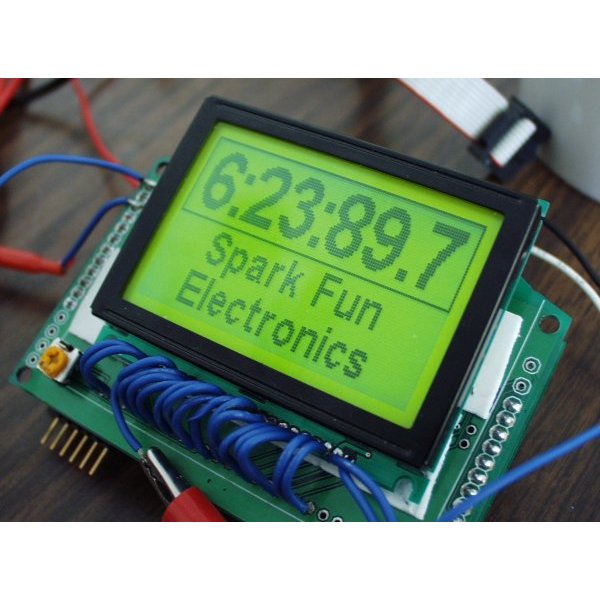
The current version of this graphic display (GDM12864H) has a unique feature that I have not seen in any other 128x64 graphic LCD. Its pixels (and pitch) are square (0.39x0.39mm) so your circles appear as circles -- no more ellipses!!!
Wonderful GLCD, I did beautiful clock using this GLCD
http://sites.google.com/site/abdulla877/about/pic-tutorials/glcd-clock
Abdullah
Hi,
Thanks for posting. Please explain why you have 2K ohm connected to the V0 and VEE pins? This LCD has built-in DC converter to drive the LCD already?
Thanks!
I believe he choose a 2k instead of a pot to adjust the contrast. I'd keep a pot, perhaps a 10K on there to adjust it if you please.
Someone noted above that the voltage needs to be fairly low (~-4V) to see the darkness of the pixels. If you hook a pot up, be sure to wipe it to both extremes to see if you can atleast see a big black box when the LCD has power, then you know atleast your contrast works and you're getting power!
Does anyone have any code/examples on how to make this work with a msp430??
I would also like to see some!
I ported the Arduino's ks0108 library to the MSP430 and have it working. If you're still interested in the code feel free to ask me. At some time I should put it up for public consumption but it's not ready yet. With that said I'm still willing to share what I have if people are interested.
astromme - I am currently working on a project with this serial graphic display and I am interested in using the MSP430 could I get a copy of the adapted Arduino ks0108 library? Thank you, this would be greatly appreciated.
Hey do you still have the working code for the MSP 430. I have spent 3 days trying to make it work and I can't. If you could please post it.
Thanks
I haven't found anything for the msp430 yet... a simple example of how to put a mere pixel on a specific point in the screen would be awesome!!
really really really i need help for turn it on with my Arduino uno .. the datasheet not help me " (
You should look on the product page's documents. There's links to get it working with an Arduino microcontroller. Also, there is an article on Arduino if you did an online search with example code and a hookup guide => http://playground.arduino.cc/Code/GLCDks0108.
The App Note link is dead.
Hmm, I just noticed that. I'll put in a bug to fix this issue.
I posted a video showing how to get up and running quickly with any ks0108 lcd on AVR's using the library from http://en.radzio.dxp.pl/ks0108/
https://www.youtube.com/watch?v=sxDUXLiOuPw
Just remember that if you connect the RES pin to your MCU like I did, you'll have to add code to this library to bring it high during initialization, or add an extra routine to make use of it.
Can this be used in direct sunlight? If not, any alternatives that would do the trick?
Do Netduino examples exist.
HI, can the product be interfaced with a spartan 3 FPGA ?
Is this compatible with raspberry pi?
Has anyone set one of these up to run off 2 74HC595 chips to reduce the number of wire going to the Arduino?
it is fun to deal with SPARKFUN.
Please refer our internal part # LCD00007. PO#6345
Does anybody have problems with the text cutting out after maybe 30 seconds of use?
this work with USB13700?
I'm a little late to the party here, but I'm having some issues with stability. It doesn't like when I reset my uC (Mega644P). I'm using code derived from summoningdark's upgraded firmware. When the screen decides to work, it's great. Sometime if i have a scope on one of the pins it starts just fine. Doesn't matter which pin. On my scope, I see a lot of noise on the pins. Stuff way below the 5v it's running on. Any special tricks? Reset operations? Pullup/Pulldown resistors, filter caps?
Can this be used with an Arduino Duo directly? or will i need some level shifters to convert between the Arduino's 3.3v and 5v?
Is this bright enough for use in direct sunlight?
I recently bought this LCD to use with a Maple Mini board. What Library should I use with it? I found the KS0108 Graphics LCD library on the Arduino page. That seems to be more useful than the LiquidCrystal library which doesn't seem to work with this 20-pin LCD.
Great screen for playing around with on the Arduino. There's a full-featured library available with some example sketches to test that your screen is wired correctly. The only downside is that the parallel interface takes up almost all of the pins of the Uno.
The one i ordered off sparkfun nearly a month ago was of the " small fraction of the glcds out there will need a reset pulse" variety? it took me a few days and several hours to realize, i had to waste another pin. The solution was to go into the library and un-comment part of the code as described at the bottom http://www.arduino.cc/playground/Code/GLCDks0108/
edit: also got this to work on a mega, but it needed the reset pin unlocked as well.
connecting the reset line to Vcc works for me
Utility Meter App Note link is broken.
...and the Serial Graphics LCD App Note...
Hello, Has anyone tried taking it apart and change the backlight color? If so, how hard is it?
I'm looking for a similar specs LCD, but with a white or blue backlight.. I'm planning on adding it next to my motorcycle OEM screen, and being green would quite likely be an ugly mismatch.
Thanks in advance.
Actually, please ignore my previous comment. I think I found exactly what I was looking for. http://www.sparkfun.com/products/10133
Does anyone know, LCD with same for technical specifications and size with this LCD but has color display? Thank You
Just can't make mine work. Just received it a while ago and have tried all the suggestions here and nothing. It just starts with all the pixels black and remains like that.
I recommend using the Graphic LCD Serial Backpack and with a firmware upgrade the perfomance is pretty sweet, thanks to SummoningDark's firmware.
For information on how to upgrade the firmware look at my post at the Arduino forum
Hi all,
I finished from building a portable oscilloscope by using this wonderful GLCD, check it hear:
http://www.pic-tronics.com/PIC-Based-Oscilloscope.php
regards
Any idea when these will be back in stock?
I second this. I could really use one in the next week or so.
I'll take 1 too!
has any one used this with a picaxe
Hi,
Datasheet mentions (p6) that KS0108B "Input High Voltage" is 2.0 to Vdd (V) for pins CS1B, CS2B, CS3, E, R/W, RS, DB0~DB7.
My LCD is powered by 5V supply, I would like use a PIC@ 3.3V to drive it.
Does someone experienced to drive this LCD (GDM12864H) with 3.3V signals ?
Thanks :)
I have successfully used an AVR @ 3.3V to control this LCD. I would agree that according to the datasheet this can be expected to work.
Perhaps the datasheet has changed in the past year, but I see "Logic Supply Voltage", "Operating Voltage", and several others listed as 4.5V Min, 5.0V Typ, 5.5V Max.
I can also confirm after owning one, and attempting to interface with a PIC32MX795F512L that it will not function properly on 3.3V logic. Even removing the PIC from the setup and manipulating the I/O lines by hand, I saw improper behavior with 3.3V and proper behavior with 5V.
Any idea when these will be back in stock? I accidentally blew my last one up (overvoltage, poked the jumper in the wrong rail on the protoboard!) and now I'm getting behind on the project!
I second that! There hasn't been any in stock since the 25th of feb!
Oops! just restocked minutes later!
lol just sth cool you can do with a lcd and an arcade-style pushbutton :D Running Mario http://joekwuen.blogspot.com/2011/01/project-pic-button-mashing-game.html?spref=fb
I have simple text driver for PIC.
get the source code from
http://joekwuen.blogspot.com/2011/01/project-pic-lcd-module.html
I have written a simple tutorial to get this LCD working with Arduino if anyone needs help - http://wp.me/pQmjR-1fR
hey guys: does anyone have code to use this LCD with an MSP430......
This is exactly what I have been looking for to hook up to a Ybox (I just want a neat little gadget to hook up my workshop, nothing too big). But the question is, (and I know this is going to sound noobish, because I am, and have just literally dived into the world of electronics with a lot of information and knowledge already but less than a month's experience) would it be compatible?
Has anyone used this LCD with an mBed? If so, could you post some sample code?
If you wanna see a fast project with this LCD and an Arduino go here:
Photos:
http://saki-tech.tumblr.com/post/509580787/this-is-my-christmas-project-for-my-little
Video:
http://saki-tech.tumblr.com/post/509605082/this-is-the-video-of-my-s-m-s-project-in-action
And electric scheme:
http://saki-tech.tumblr.com/post/513311661/electric-scheme-of-s-m-s-project
Enjoy it! ;)
Bought without thinking, I need power from 0ne Li-ion battery. What's the maximum current this unit takes and is there a simple ways of operating from 3v3 (besides DC-DC converter)?
It looks like it can draw a max of 420mA.
That's a dent in my battery life then
Can the LCD be removed from the PCB? I'd like to use this as a very low res projector LCD with a higher power backlight and lens assy.
I don't believe ones like this will work in that manner, it won't be clear enough.
I wired mine up exactly how it is shown in the pong clock app note. when I try to give it power it starts to draw more then one amp with my power supply at less then 3v. I've checked my wires a few times to make sure they match the schematic on the app note.
Is my LCD dead?
Make sure that you have a 100 to 330 ohm resister in series with the LCD backlight. Some of the documentation is not clear on this, but the resister must be there or the LED backlight will act like a dead short as soon as the voltage rises above the LED forward bias - usually about 2.0V.
Any idea when this will be back in stock?
So, stupid question, the LCD screen says it needs 9V to work. Is that supplied by the circuits on the board, or do you need to create a step-up dc converter to change 5V into 9V?
This product has very good app note thanks Sparkfun
I've done exactly as csloser did in his tutorial, but i am also having difficulties getting it to work properly. I'm running it on a ATmega168.
While the microcontroller was running, i had to take the display off my test board, because (stupid as i was) i mounted the V0 pot-meter under it. When i connected it back it was working!
So now i can get it to work, but only if i pick it out and put it back in a couple of times, or cycle the power... I have no clue why it is like this, but maybe you other guys can do the same, and see if it helps.
PS: If i press the reset button which i have connected to the LCD while it's working, it stops working again, and i have to cycle the power... :(
I tried this method, without success. Obvious resets and power cycles do nothing, as well.
I just ordered the damn usb logic analyzer from SFE, so I should be able to debug what the hell is going on. I will post back here if I come up with anything. Hopefully we are all having the same problem. :)
Ok, so I've had my analyzer for a day now, and it helped me figure out that PORTA on my MCU is a pile of crap. The LCD seems fine after all.
I can't recommend this analyzer highly enough, after this experience:
http://www.sparkfun.com/commerce/product_info.php?products_id=8938
I'm going to have to throw my hat into this with GeodeLX and InkAnkUnk. I can't get so much as a pixel out of this thing, using Csloser's AVR code and having checked and rechecked wiring N times. Writing my own library from scratch from the datasheet also results in absolutely nothing. At least the backlight and contrast adjustment via pot works.
I have tried Csloser's AVR code, but all I get is one horizontal line, the top most specifically to write. I have hooked the output of my DB0 - DB7 to an oscilloscope to confirm I am writing. I have also confirmed this corresponds to my CS1/CS2 signal. has anyone else had this issue?
On the page Csloser links to, he recommends a pull down resistor. Could anyone comment on the importance of this? Could this be the cause of my one line LCD?
Thanks in advance for ANY help.
I purchased one of these and hooked it up to my Arduino Mega according to this page:
http://www.arduino.cc/playground/Code/GLCDks0108
I grabbed the software and loaded it. The backlight works and at first I saw a few lines on the display itself (these faded). When I ran the software from that web page, nothing came out on the display. I played with the contrast potentiometer a little, but I still see nothing. The program is running (I added some Serial output for debugging).
Is it possible that I burned out the controller? Or... is it possible I just got a bad one? Does anyone have experience with these that might be helpful?
Thanks!
There is a very good chance you just haven't done something right. I had some trouble getting it to work as well, but it was because the code wasn't doing the right thing. I design and develop my own boards so I have no experience with the Arduino, but if you have a more specific question I can attempt to help you.
Vo can be connected anywhere from -5V to +5V. As long as you didn't connect it to a voltage outside of that range, it should still work.
I forgot to mention that the LCD voltage, in my experience, should be around -4V for the display to be readable. Close to -5V will turn all of the pixels fully on and above -3V they will be totally transparent. Other units may behave differently but this is how mine works.
Thanks for the info. I was quite careful about the voltages being supplied to the LCD, but I'll check again (and verify the contrast voltage).
Any idea when this will not be on backorder?
Additionally, a tremendous amount of useful information pertaining to that library can be found in the Arduino forum discussion:
http://www.arduino.cc/cgi-bin/yabb2/YaBB.pl?num=1210427907
does anyone have the code for this to use with arduino???????
for those interested, there is a link in the Arduino playground for controlling KS0108 graphic displays!
http://www.arduino.cc/playground/Code/GLCDks0108
I intended to drive this LCD with an ATmega168, which now appears to be an astonishingly bad idea if the uC has only 1K RAM and you need that to drive the LCD. True? Or am I missing something completely obvious to the non-novice? It looks like I need a separate uC (like the DiosPro) to drive the LCD, with the 168 uC controlling the DiosPro via the UART? Happy to take advice....
You don't have to devote any ATmega168 RAM to the LCD. This component has its own video RAM, one bit per pixel, 512 bytes total. I think you have to write whole bytes at a time (8 pixels), and it doesn't know how to draw a letter "A" by itself, but the App Note from Kronos Robotics says they have a higher-level Dios library to deal with such operations.
I have a tiny oscilloscope I bought from another vendor, it looks like this part is identical to the screen they use.
How bright is this LCD? Can it be used outside?