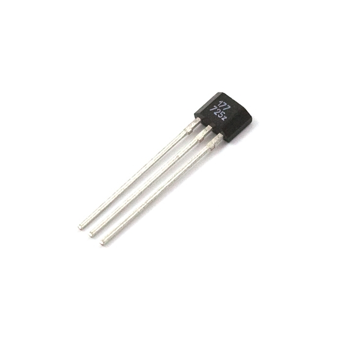
Home | Product Categories | Magneto | COM-09312

Hall Effect Sensor

sku: COM-09312 RoHS Compliant

Description: 
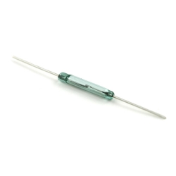
The US1881 is an integrated Hall effect latched sensor. That's nice but what does it do? Holding a magnet near the sensor will cause the output pin to toggle. This makes for a robust presence sensor. A reed sensor also works nicely, but can be limited by the glass encapsulation and size. A hall effect sensor is much smaller, but can handle less current than a reed switch.

The device includes an on-chip Hall voltage generator for magnetic sensing, a comparator that amplifies the Hall voltage, and a Schmitt trigger to provide switching hysteresis for noise rejection, and open-collector output. An internal bandgap regulator is used to provide temperature compensated supply voltage for internal circuits and allows a wide operating supply range.
 
If a magnetic flux density larger than threshold Bop, DO is turned on (low). The output state is held until a magnetic flux density reversal falls below Brp causing DO to be turned off (high).

Features:

  • 3.5V to 24V DC operation voltage
  • Low current consumption
  • Temperature compensation 
  • Wide operating voltage range
  • Open-Collector pre-driver
  • 50mA maximum sinking output current
  • Reverse polarity protection
  • Lead Free Package: TO-92

Documents:

Pricing

In stock

0.95
0.86
0.76

1,261 in stock

price
10-99
100+


Add to Wish List


Comments 30 comments

  • any plans for sparkfun to carry non latching hall effect sensors? I’d rather not pay shipping to two different retailers.

    • plz??????? :)
      here is a picture of a cat to convince you.
      (http://images.paraorkut.com/img/funnypics/images/l/lol_cat-12926.jpg)

  • Spark fun clearly don’t give a dam but I was able to find some more information with this latest datasheet.
    You’ve got 3 pins from the front (the triangle edge). Left to right, power, ground, output.
    Stick a 10k pull up between 5v and output. Then it’ll latch on/off depending on the poll you use.
    hope that helps

  • Pay attention to the pin out on the data sheet ;) There are two sensors (surface mount and through-hole) with different pin designations.

    • This. I had it correct in my prototype, but misread the sheet for the production install. What a pain. You want the second column for through hole (UA Pin No).

  • Yes, this hall effects sensor latches on/off depending on the polarity introduced to it. I needed it to latch on/off when a magnetic field was/was not present, which this is not set up to do by design. But I found a simple way around that…
    I am using the sensor with an Arduino, so my implementation may not work for your setup. Instead of providing constant power (5v) to pin 1, I instead connect it to a digital pin that I have set as an output. Pin 2 goes to ground and pin 3 is read as a digital input. Note: As mentioned in other comments, I use a 10k pull-up resistor between power (digital out to pin 1) and output (digital in from pin 3) to get a clear on/off state.
    In the loop code, I first set the hall sensor power pin to HIGH and delay for as short as 10ms, read the latched state from it (on/off), and then set the hall sensor power pin to LOW and delay another 10ms.
    Cycling the power resets the state of the sensor so you can poll its output to see if the magnetic field (of the polarity that latches it ON) is still present or not. The delays are necessary to give it time to reset, otherwise it will give unexpected results.
    This allowed me to make a simple open/closed presence sensor without having to do something funky with the magnet to get it to flip poles each time. I hope this helps!

    • Nice post. I used your hardware setup and did the same thing. Works great. I tried to use smaller delays but I too arrived at 10ms as a good interval to allow the sensor to reset.

      • I just used this technique as well. It’s perfect. It may be a good idea to put this up as a link in the documents section for the part.

  • any plans for sparkfun to carry non latching hall effect sensors? I’d rather not pay shipping to two different retailers.

  • Yes, the ATS177 is a latching sensor that requires a reverse field to turn it off.
    I would like to see the Allegro A1301EUA-T Hall Effect Sensor. It is a continuous-time, ratiometric, linear Hall-effect sensor optimized to accurately provide a voltage output that is proportional to an applied magnetic field. It has a quiescent output voltage that is 50% of the supply voltage and provides 2.5 mV/G.

    • Non-latching and omnipolar would be a nice option, too; I opted for a Honeywell SS451A, which I tested successfully with the Arduino. (Ratiometric would be cool, but not necessary for what I have in mind, so I went for simple.)

      • that’s useful, thx for posting. do you know of equiv parts available at jameco? they have 30 varieties but none appear to be omnipolar. their parametric search sucks so hard to be sure.

    • Yeah, some analog sensor to measure the distance to a magnet would be very handy!

  • Has anyone got a schematic and possibly some pictures for this sensor. I’m trying out the schematic in the Datasheet but the Arduino isn’t having any of it :(

  • http://www.melexis.com/Assets/Hall_Applications_Guide__3715.aspx
    so this is the first breakthru I’ve had.

  • I would like to second the need for a non-latching sensor.

  • I am also looking for a non-latching sensor.

  • This sounds like one of those hall effect sensors that requires a field reversal to turn off – in other words, a south pole latches it high, north pole returns it to low.

  • Anyone having any luck with the Arduino and this sensor?

  • ^^ He’s actually right about the datasheet. I just tried using that on mine and it FINALLY WORKED!

  • Hi all..
    I am new to this forum.
    I brought above Hall Effect Sensor from sparkfun & built circuit as per datasheet above, ie “Typical Three-Wire Application Circuit”.
    I am using normal fridge magnets. Against my expectations, to get 0 & 5V ouput at pin 3 of sensor, I observe only 0 & 0.5V output(Supply voltage +5V DC).
    Is it due to normal fridge magnets?
    How do I get 0-5V output?
    Thanks everybody,
    myetrx

  • I had a heck of a time getting these to work reliably for me with an arduino. I tried all kinds of code tweaks and wirings and eventually gave up and went for the much simpler reed switch (which I didn’t know existed at first) and now my project works great!
    http://www.youtube.com/watch?v=kAReep0QhpU

    • Nice work! For some things a reed switch is just plain easier and simpler to use. Each has its own application.

  • Heres the circuit i use to interface this chip to a pic microcontroller: Connect the Hall effect sensor to Ground (middle pin) and power (left pin from triangle side). Then connect the hall effect output (right pin) to both power (Vdd should about 5 volts) through a 10k resister (R1) and to the noninverting input of a 741 op amp. Next connect the inverting input of the op amp to to ground through a 100 ohm resistor (R2) and to the op amp’s output through a 10k resistor (R3).
    This circuit should amplify the voltage by a factor of 11 (see wikipedia non-inverting amplifier for more detail).
    Testing showed the circuit output at 4-5V when the hall effect sensor was latched on and under 2V when latched off. -John Fitz

    • EDIT: change R2 form 100 ohm to 1k ohm

    • To add to this suggestion… Rather than multiplying the output voltage, I’ve gotten better results feeding it into an op amp comparator, like this:
      http://en.wikipedia.org/wiki/Operational_amplifier_applications#Comparator
      V1 comes from the pulled-up Hall sensor output, and V2 comes from a voltage divider set to give 250 mV. The output will go to one rail or the other depending on the sensor’s output.
      This setup has a couple of advantages. First, it goes all the way to GND and VCC. Second, if you have more than one Hall sensor, it will require only one voltage divider (one op amp per input with the voltage divider’s output going to each one).

  • When I ordered these for my rain gauge project, I missed the word “latched” in the description! Perhaps SparkFun could change the part name to “Latched Hall Effect Sensor”?
    Fortunately, I also ordered 2 reed switches that should work for my project. I’ll have to find something else to do with these, or use the method suggested by JPFlash for resetting the latch by controlling the power with a Digital Output. I thought that was a clever idea.

  • Sparkfun—

    Can we please have a linear analog or non-latching digital hall sensor? The Bildr tutorial you list references both types of hall effect sensors as well as yours sold here. An analog sensor may be easier to use as the problem of dealing with open-collector outputs (as seen here) will be gone; only a voltage must be fed into an ADC.

    Thanks! baum

    p.s. in fact there are very cheap ($.85) non-latching sensors on mouser…