SparkFun Serial Basic CH340C Hookup Guide
 Elias The Sparkiest
 Introduction
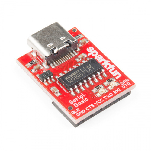
The latest iteration of the SparkFun Serial Basic Breakout takes advantage of USB-C and is an easy-to-use USB-to-Serial adapter based on the CH340C IC from WCH. With USB-C you can get up to three times the power delivery over the previous USB generation and has the convenient feature of being reversible. The product works with 5V and 3.3V systems and should auto install on most operating systems without the need for additional drivers. The Serial Basic uses the CH340C IC to quickly and easily convert serial signals to USB. It’s a great lower-cost alternative to the extremely popular FTDI Basic.
Required Materials
At a minimum, you will need the following materials to follow along with the tutorial. You may not need everything though depending on what you have and your setup. Add it to your cart, read through the guide, and adjust the cart as necessary.


Suggested Reading
Before you begin it may be worth looking at the basics of Serial Communication. Do you have a favorite terminal program yet? No? Take a look at the Serial Terminal Basics tutorial which will give you a brief introduction to popular Terminal programs.
Serial Communication
Serial Terminal Basics
How to Work with Jumper Pads and PCB Traces
Serial Basic Overview
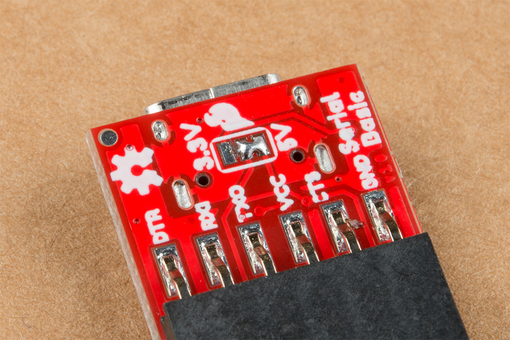
The pinout of the Serial Basic mimics the common DTR/RX/TX/VCC/CTS/GND pinout found on hundreds of FTDI-to-USB derivatives.
| Pin Label | Input/Output | Description |
|---|---|---|
| DTR | Output | Data Terminal Ready, Active Low |
| RXI | Input | Serial Receive |
| TXO | Output | Serial Transmit |
| VCC | Supply Output | Power supply 3.3V (Default) or 5V |
| CTS | Input | Clear To Send, Active Low |
| GND | Supply Output | Ground (0V) supply |
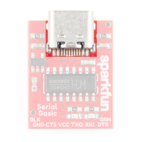
USB-C
USB-C gives you the potential of more power than the previous generation of USB. USB-C is used to power everything from laptops to low powered micro controllers and has the amazing capability of being reversible.
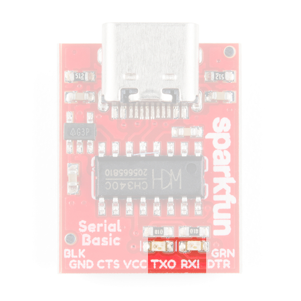
LEDs
The two LEDs on the board are connected to TX (Green) and RX (Yellow) and are correctly aligned to the silk header labels: RXI and TXO . This is a quick and handy way to see the serial traffic.
Alignment Markers
The GRN and BLK silk in the corners opposite of the USB-C connector, is there to help you align the board properly with products that use these same orientation indicators.
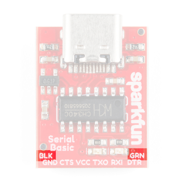
The Serial Basic mates seamlessly with products that use the standard serial connection. If you see a board with the BLK and GRN labels, then you know it will be compatible with the Serial Basic.

Voltage Selection Jumper
There is a jumper on the underside of the board that controls the output voltage on the VCC pin. By default, the board outputs 3.3V and has 3.3V signals.
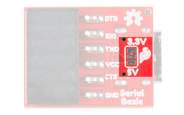
3.3V. When the jumper is set to 3.3V, the board uses an on board 3.3V regulator capable of sourcing 600mA. If you attempt to pull more than 600mA, the regulator will go into short-circuit shutdown where it will only output 150mA.
You can change the board's output and signal to 5V by cutting the trace between the center and 3.3V labeled pad and putting solder on the center and 5V labeled pad. This will change the board's output to 5V on the VCC pin with 5V signals.
When the jumper is set to 5V, the board will source as much power as your USB port will provide. With USB-C this can be up to 1.5Amps but depending on what is providing the power and the capabilities of your cable, you can get up to 3 Amps.
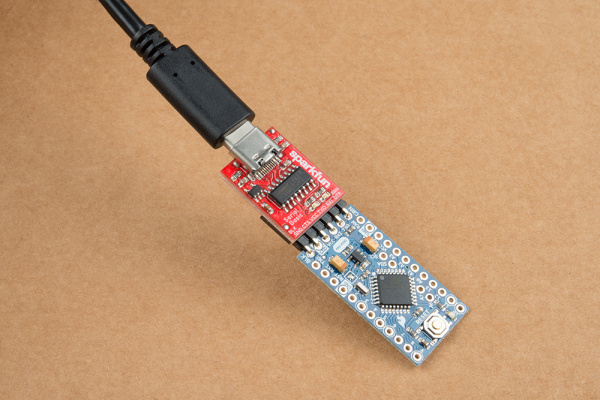
Hardware Test
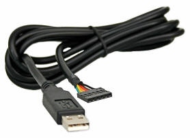
To connect the board to a computer, you will need a USB-C cable. Plug the USB-C cable into a USB port on your computer and the other end into the Serial Basic. Your computer should automatically install the necessary drivers and create a COM port on your computer. If you are prompted for drivers, please see the Drivers section.
The quickest and easiest way to make sure everything is working is to do a TX/RX loop-back. To do this, insert a jumper wire between TX and RX as shown below. Anything that is transmitted from the TX pin will be echoed back to the RX pin.
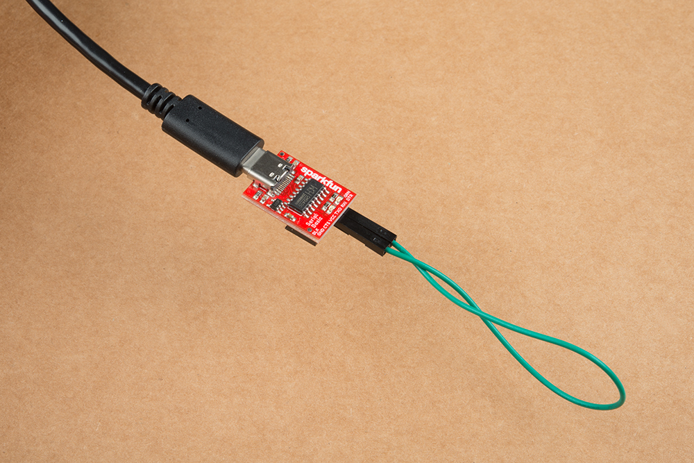
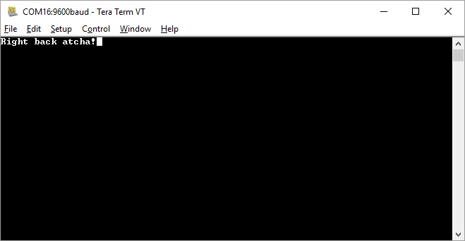
Now that you've got that plugged in, open your favorite terminal program. Select the COM port that the Serial Basic is assigned to, and connect. When you type a character, you should see each character you type echoed back in the terminal and the RX and TX LEDs will flash as you type.
Which COM Port Do I Need?
Most programs will show you a description of the USB device that created the port. To verify that your driver is working, you can use a serial terminal, Arduino IDE, device manager, or command line.
Serial Terminal
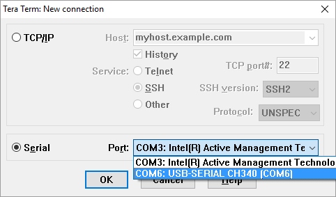
Look for the port associated with CH340C. The image below shows the Serial Basic enumerating on a COM port within a serial terminal.
Arduino IDE Ports
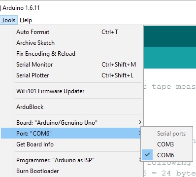
If you're using the Arduino IDE, figuring out which COM port is the one you want is more difficult. Here's the quick way to figure it out: attach the Serial Basic to your computer, and check which COM ports are listed. In the image below, we have two ports. Now close the Tools menu by clicking on the main Arduino IDE window.
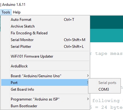
Unplug the Serial Basic, and re-open the Tools -> Ports submenu. You will see one of the serial ports is missing. That's the one you want! Plug your Serial Basic back in, and use that COM port.
Windows: Device Manager
You can also verify that the board is installed if it shows up in your device manager. You can click the Start or ⊞ (Windows) button and type "device" to quickly search for the application. (*On Windows 10, the quick search function is picky on the spelling of the application you are searching for. For example, you may get results using "_devi_" and none for "_device_".)
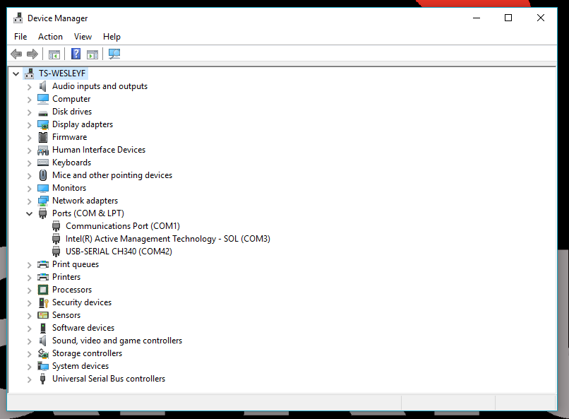
Screenshot of Window 10 Device Manager with Serial Basic on COM42. Click to enlarge.
Mac OSX: Command Line
To verify on a Mac via the command line. To open a command line window, head to your Applications folder, Utilities folder, then double-click on Terminal. Otherwise, press ⌘ (Command) + space bar (Space Bar) to launch Spotlight and type "Terminal," then double-click the search result.
Run the following command "ls /dev/cu*" in a Terminal and check for the following changes (your board may show up under a different device name).
language:bash
ls /dev/cu*
You should get something similar as shown in the image below.
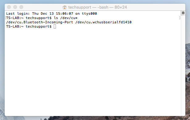
Screenshot of Mac OSX terminal with Serial Basic on cu.wchusbserialfd1410. Click to enlarge.
Raspbian: Command Line
Run the following command "ls /dev/ttyUSB*" in the CLI/Terminal and check for the following changes (your board may show up under a different device name).
language:bash
ls /dev/ttyUSB*
You should get something similar as shown in the image below.
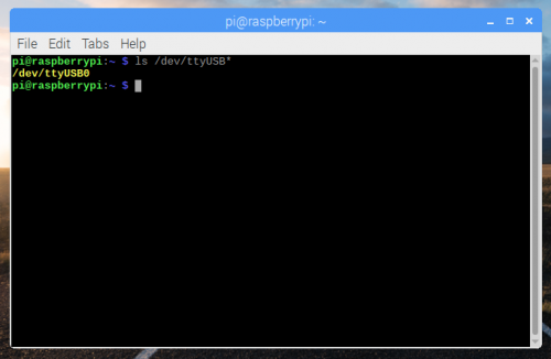
Screenshot of Raspberry Pi CLI with Serial Basic on ttyUSB0. Click to enlarge
Drivers (If You Need Them)
The driver should automatically install on most operating systems. However, there is a wide range of operating systems out there. You may need to install drivers the first time you connect the chip to your computer's USB port or when there are operating system updates. For more information, check out our How to Install CH340 Drivers Tutorial.
How to Install CH340 Drivers
August 6, 2019
Resources and Going Further
Once you've got serial communication working, you're ready to start playing with serial projects. Consider connecting to a GPS module like the GP-20U7, taking a look at our tutorial on GPS and watching the serial strings roll by. Or, you can use the Serial Basic to program and debug devices like the Arduino Pro Mini. There are tons of devices that use serial to communicate, so go explore!
Check out these other resources for the Serial Basic.
- Schematic (PDF)
- Eagle Files (ZIP)
- Datasheet (PDF) (CH340C)
- Fritzing Part (FZPZ)
- WCH: CH340 Drivers - Latest drivers can be found from the manufacturer
- Windows (EXE) -- Driver executable
- Windows (ZIP) -- Driver version 3.4 (2016-09-27)
- Linux (ZIP) -- Driver v1.5 (2018-03-18)
- Mac (ZIP) -- Driver v1.5 (2018-07-04)
- GitHub
Check out these other great SparkFun tutorials.
Qwiic Differential I2C Bus Extender (PCA9615) Hookup Guide
SparkFun Serial Basic CH340C Hookup Guide
Three Quick Tips About Using U.FL
Need some inspiration for your next project? Check out some of these related tutorials: