- Home
- Product Categories
- Power Charger
- SparkFun Battery Babysitter - LiPo Battery Manager

SparkFun Battery Babysitter - LiPo Battery Manager
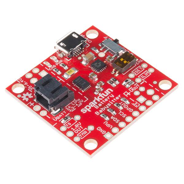
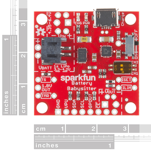
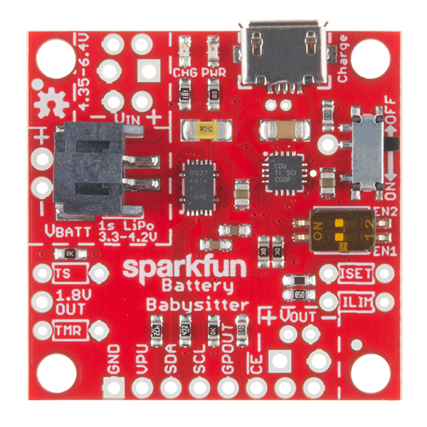
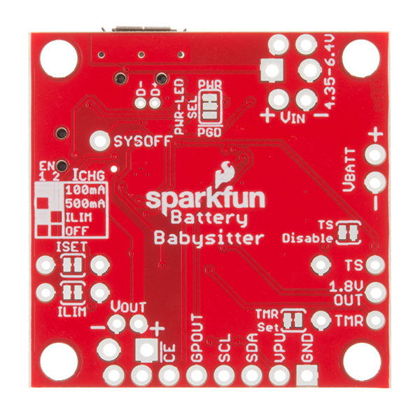
The SparkFun Battery Babysitter is an all-in-one single-cell Lithium Polymer (LiPo) battery manager. It’s half battery charger, half battery monitor, and all you’ll ever need to keep your battery-powered project running safely and extensively.
The Battery Babysitter features a pair of Texas Instruments LiPo-management ICs: a BQ24075 battery charger and a BQ27441-G1A fuel gauge. The charger supports adjustable charge rates of up to 1.5A, as well as USB-compliant 100mA and 500mA options. It also features power-path management, guaranteeing power to your project even if the battery has died. The self-calibrating, I2C-based BQ27441-G1A measures your battery’s voltage to estimate its charge percentage and remaining capacity. It’s also hooked up to a current-sensing resistor, which allows it to measure current and power! It’s a handy IC to have, if you ever need to keep an extra eye on your project’s power draw.
- LiPo Charger and LiPo Fuel Gauge combined into one board
- DIP-switch-selectable charge rates of 100mA, 500mA or 1.5A
- MicroUSB port for charging, or external options
- Dynamic power-path managment maintains a reliable output supply
- On/Off switch disconnects the battery for more power saving
- 5V-tolerant I2C interface to fuel gauge
- Fuel gauge measures voltage, percentage, and current
- Schematic
- Eagle Files
- Hookup Guide
- Datasheet (BQ24075 Charger)
- Datasheet (BQ27441-G1 Fuel Gauge)
- Arduino Library
- GitHub
SparkFun Battery Babysitter - LiPo Battery Manager Product Help and Resources
Battery Babysitter Hookup Guide
June 23, 2016
An introduction and getting started guide for the Battery Babysitter - a flexible LiPo battery charger and monitor.
Core Skill: Soldering
This skill defines how difficult the soldering is on a particular product. It might be a couple simple solder joints, or require special reflow tools.
Skill Level: Noob - Some basic soldering is required, but it is limited to a just a few pins, basic through-hole soldering, and couple (if any) polarized components. A basic soldering iron is all you should need.
See all skill levels
Core Skill: Programming
If a board needs code or communicates somehow, you're going to need to know how to program or interface with it. The programming skill is all about communication and code.
Skill Level: Rookie - You will need a better fundamental understand of what code is, and how it works. You will be using beginner-level software and development tools like Arduino. You will be dealing directly with code, but numerous examples and libraries are available. Sensors or shields will communicate with serial or TTL.
See all skill levels
Core Skill: Electrical Prototyping
If it requires power, you need to know how much, what all the pins do, and how to hook it up. You may need to reference datasheets, schematics, and know the ins and outs of electronics.
Skill Level: Rookie - You may be required to know a bit more about the component, such as orientation, or how to hook it up, in addition to power requirements. You will need to understand polarized components.
See all skill levels
Comments
Looking for answers to technical questions?
We welcome your comments and suggestions below. However, if you are looking for solutions to technical questions please see our Technical Assistance page.
Customer Reviews
3.8 out of 5
Based on 10 ratings:
4 of 4 found this helpful:
Decent, but probably still better than the alternatives
Would be nice if it included a step-up DC/DC to provide a constant 5V output, like the "SparkFun LiPo Charger/Booster - 5V/1A", while retaining the coulomb counter/fuel gauge - especially for the price.
My main concern is that the copper pour on the bottom of the PCB around the charging IC is very small, so that spots gets rather hot when charging at 1.5A from a 5V source. This should've been a 4 layer board with a solid copper pour on the bottom side and lots of vias to conduct that heat away.
In any case, the coulomb counter is very useful to minimize power consumption in a battery powered project.
P.S. - The hookup guide claims the default charge rate is 1500mA - it appears to be 100mA.
Thanks for the feedback and review. In terms of the charge rate listed in the hookup guide, you are correct. By default, the switches should be in the ON position from the supplier which would set it at 100mA. Our production does not adjust the switch under the test procedures since it is under the pick-n-place yellow film.
I verified it against the boards on storefront and checked the schematic. The tables (for the “Charge Rate” and “Power Path Operation Modes”) and associated paragraphs in the tutorial have been adjusted to reflect this information.
1 of 1 found this helpful:
Have yet to work with it
But looking for documentation; beyond that, the build quality is excellent on the rash of products I just ordered! Arrived exactly on time!
The big thing I wish I had gotten was a list of practical connectors that pair with the board. I need to find connectors to solder onto my battery terminals, etc.
Very much looking forward to plugging this into my setup once I find the de-facto documentation.
1 of 3 found this helpful:
NOT as advertised.
Be warned: the documentation says they are using a BQ24075. If that were true, according to TI's docs, it would have 5.5v regulated output, not this funky battery-dependent voltage. I bought this specifically because it had this feature, but it doesn't. I've made a couple of attempts to contact Sparkfun for clarification, but have been effectively ignored at this point.
ALSO: If you try to use this on a device that doesn't already have a library for interfacing with the BQ27441-G1A over I2C, GOOD LUCK. TI's documentation on this is difficult to understand at best.
I can positively verify that there is a BQ24075 IC on the Battery Babysitter. The full part number for the IC on the board is BQ24075RGTR and we get them in reels directly from a well know and respected TI parts distributor. It's possible that our design doesn't allow for a 5.5 volt output, but I can say for a fact that there is a genuine BQ24075 IC from TI on this board.
Unfortunately I can't locate any messages or queries from you about this part. Are you sure you sent them to us? If we didn't get a request we wouldn't have responded to you. This could be why you feel we are ignoring you. I would encourage you to reach out to us on our forum if you have more questions and we will do our best to answer those there.
Works OK but has quirks
Battery voltage measurement resolution is great at 3 decimal places to the right. Current and Power measurement are also great with polarity and 5 digits of resolution. Battery Temperature measurement doesn't seem to be reading anything that I can tell. Tried different wiring on TS terminals and cut the jumper. Nothing changed the almost static reading 4 digits. Timers are another feature that didn't seem to follow what the data sheet says. Charge current was always MAX. Never saw Preconditioning occur. SOC is another area that behaves oddly. Never really know what the "real" state of the battery is with numbers shown. It appears to work best when connecting a "rested" battery and then monitor the discharge profile. When connecting a charger the SOC number immediately changes to something different. Makes one wonder what the state of charge really is. There are nice things about this device such as the values returned from the monitor chip are signed or unsigned 16-bit integers, which makes converting to BCD digits for a character display very easy. The 1.5 amp charger capacity is nice instead of being limited to 500 milliamps. I missed having a JST header on Vout port and QWIIC header would have been nice to have too. There is a lot to like about the very stable voltage, current and power readings this device displays with a lot of good resolution too, many digits. But the quirks that I have pointed out just take away from any confidence in using this device in a serious LiIon or LiPo project.
Works with Raspberry Pi
I’ve connected this thing to Raspberry Pi. Linux kernel already supports it.
Proper device name that I’ve used is bq27441
Perfect as expected
Work realy fine. Exemple code work well to and permit and quick use.
Works great.
I got this part after a succession of Adafruit and Amazon chargers and lipo fuel gauges. Having charger and guage on the same board is advantageous and more accurate than separate modules. I've yet explore the recommended libraries, but am under the impression that the lack of particular breakouts (charging status) can be addressed through code. Onboard micro switch is handy and it appears (after several days) that board has no load on lipo when switch is off.
Super board.... works just as advertised
Great documentation and videos. Very well thought through. Easy to hack as well.
Well done!
This will serve as the cornerstone of my battery based projects
Just want to say great job to Sparkfun for breaking out all the capabilities of these ICs. I know most of the use cases won't need a thermistor, but it is infuriating when you have a board with a capable part but it isn't in an accessible area since the designer didn't think it would get used.
Great job guys.
I was wondering if I can use this module to power a raspberry pi 3, since it seems that it cannot deliver a steady 5V (depending the battery state)?
Maybe I must combine it with a boost converter?
What if I wanted to combine this with a boost converter so I could get the output to 5V at 1A? (i.e. TPS61200) Is that possible and if so how would it be wired?
Hi there, it sounds like you are looking for technical assistance. Please use the link in the banner above, to get started with posting a topic in our forums. Our technical support team will do their best to assist you.
That being said, I've never tried it. It probably depends on how you intended to operate the two boards together.
I know the Raspberry Pi likes a 2A supply, but would this work as a long term (continuously running on grid power) battery backup option for a Raspberry Pi? I've been running one in a stable config on a 1.5A adapter for a while, now. Any thoughts or other suggestions are welcome.
!WARNING! It appears there is no over-discharge protection, or at least it is faulty on my boards, and I can't find any such documentation that it exists. The power LED on the BB shuts off when the battery goes below 2.4 V or so, but it was still draining at low current to the attached load when checked with a multimeter. I spotted this after the voltage had dropped to 1.8V on my 3.7 V LiPo! This can be quite dangerous! The simple TP4056 modules even have this feature (tested at 0.000 mA when I swapped it for the BB). I think this is very dangerous to advertise this the way it is, i.e. "handles everything related to battery charging". Maybe I misinterpreted this, but I think a lot of people are going to ruin their cells, if not worse with this lacking key battery management feature.
Hello there. I just wanted to test BB. I wanted to connect a small load and see what to do when the battery runs out. Although it seems 2833mv now, it continues to give electricity to my device. My device is not working properly now due to low voltage, but still continues to drain the battery. This is an unlikely problem with a device like this. What am I doing wrong?
I see that the minimum input voltage is 4.35V. If you used something like a solar panel (or array) that may drop below that voltage would it be bad for the chip or would it just cutoff? I'm interested in coming up with a LiPo solar charging solution that allows for unattended operation (assuming sun during the days).
Is there a good chip already designed for this that anyone's familiar with?
Thanks.
It should be well-protected against a lower-than-specced input voltages. If the input voltage is below the battery voltage, the BQ24075 will essentially disconnect the input supply from the battery-charging and output sections. There's also an an undervoltage lock-out feature, which shuts the chip off if the input voltage dips below ~3.3V. (More on that in section 9.3.1-2 of the BQ24075 datasheet.)
The Sunny Buddy might be up your alley, if you're looking for a more solar cell-specific LiPo charger.
Hi,
My LI-PO battery have a third yellow wire, mainly used for temperature measurements to my understanding. Is there is a recommendation on how to connect this type o batteries?
You can either skip the yellow wire altogether, or you can cut the 'TS Disable' jumper on the back of the board and connect the yellow wire to the "TS" pad on the board.
What is the output voltage of this if it's running with a 3.7V LiPo?
Hi, cool project! But can you elaborate why the BQ24075's TS pin is connected to BQ27441's BIN pin? According to the datasheet it should (for removable batteries) be connected to VSS, right?
Hi there, it sounds like you are looking for technical assistance. Please use the link in the banner above, to get started with posting a topic in our forums. Our technical support team will do their best to assist you.
That being said, based on the Layout Example in section 12.2 of the datasheet for the BQ27441,
BINlooks like it is supposed to be tied to the same thermistor asTSfor the BQ24075. However, in the example there is also a resistor tying it to theVss; unfortunately, the engineer on this product has since left and I cannot inquire about the thought process behind that part of the design.I bought this along with some LiFePO4 batteries, only to discover upon closer reading of the datasheet that this device can only work with batteries whose chemistry lets them go up to 4.2V. Unfortunately my project requires LiFePO4 which has a max voltage of 3.6V! There is no way to modify the output of this device to intercept the 4.2V and drop it down to 3.6V without making all the other features of the device basically pointless. Glad I read that before plugging it in to those batteries.
For anyone who's curious about the differences in chemistry, you should use a LiFePO4 chemistry for use-cases where the device will mostly get power from elsewhere (like the wall) and the batteries will be sitting at full charge for long periods of time without being exercised. LiFePO4 doesn't mind sitting at full charge for long times, unlike other lithium chemistries which will degrade faster if they're not exercised and if they're kept at full charge. (Don't keep your phone or laptop at 100%! Cycle it every day and let it "die" every once in a while).
--> Sparkfun: Please note in the product description that this device is ONLY for use with batteries that have a max voltage of 4.2V. Other lithium battery chemistries with lower voltage maximums will not work and will experience an over-voltage event if they're used with this.
Hi, everybody. Can anyone help me? Do you know if and how it's possible to add an external on/off switch to the SF Battery Babysitter? Maybe using the SYSOFF pin? I'm developping a timing system for sport; the shield is placed inside a 3D printed case and the switch on the board is not accessible. I wpuld like to completely deactivate the power output VOUT, to be sure to not drain any energy from the battery, when I'm not using the timewatch, using a swith, placed on a panel of the case.
Thank you for your help! Fabrizio
Does this board support a remote power switch, perhaps using the SYSOFF pad?
Hi All, Make sure you your battery bank capacity no exceed 8000mAh as BQ27441-G1 max is 8000mAh. Having more wont harm the chip but it will mess-up the readings like SOC Capacity etc. Did anyone upgraded this board with a high capacity chip from Ti? Any suggestions?
Maximum of how much current can this deliver? Anyone had done a test on it?
I'm a little confused about the 4 parameters recommended to be set in the data sheet for the BQ27441 on power on. I understand the Design Capacity (in my case 400mah) and Design Energy (400mah * 3.7). Terminate Voltage I'm a little less clear on what a good value is for a SparkFun 400mah battery, maybe 3.8v? Higher? Taper Rate, I'm not really sure I understand how to compute. In the data sheet, they talk about using the Taper Current to compute the Taper Rate, but I'm not sure how to figure out the Taper Current for a SparkFun 400mah battery. Thanks for any help!
Is it posible to drive the CE pin using the PGOOD output? I intend to use the bq2407 IC with a power source with unsteady voltage, and the PGOOD output seems to detects when the voltage source is good enough for charging a battery.
Can this charge 3 of these: https://www.sparkfun.com/products/13855 if parallel to get 6000mah?
I'm using this board with a Photon and the libraries are working happily. One thing I've noticed is that when the battery is fully charged and still on external power, the voltage and state of charge are both reported as 65535. I understand this is the maximum value for an integer variable, so I could just read it as "full", but I was wondering why the exact values are no longer given in this condition.
Excellent board by the way.
Hello! The BQ27441 Fuel Gauge is a flash-based part, which means it has its own firmware that can be updated if you want to better suit your particular battery or application. My former employer has allowed me to open-source a project I made that allows you to use an Arduino or Energia compatible processor to program flash-based gauges. Here it is.
If you want to do this, or want more information about this chip and why you'd want to program it, see the Technical Reference Manual, which should probably be added to the product description.
One word of warning: flash-based gauges can be permanently bricked if you program them with bad firmware. TI recommends that if you try to program a flash-based gauge, you should have several on hand in case one is rendered inoperable. I probably destroyed at least 10 gauges when I was debugging the sketch.
Oops, I think the BQ27441 is a ROM-based part, so it may not support the firmware updates that TI's other Flash-based fuel gauges do.
Oh well; perhaps my program will benefit others experimenting with TI's other parts :)
Is it ok to have the battery always in here? As in, while charging, under load, on standby.
Is it possible to talk to more than one BQ27441-G1A on the same I2C bus , I looked through the data sheet but don't seem to see if its possible .
Not easily, unfortunately. Unlike a lot of I2C chips, the BQ27441 doesn't have an address-select pin or otherwise configurable I2C address. In lieu of separate I2C buses you could use an I2C multiplexer (for example) between a microcontroller and the pair of BQ27441's.
I purchased this an a TeensyLC for a project I'm working on. I was wondering if it is reasonable to split an incoming USB connection to feed the data lines directly to the Teensy, the power lines to the Babysitter, and have the Babysitter provide power to the Teensy, regardless of the USB connection?
I am curious why my battery is not being detected? Has anyone else had any issues with this? If I could get it to be detected (BIE status pin = 1 in the Control () Flags register) then I could take measurements on my device!
I NEED HELP!
Sincerely, Michael
Is anyone else having an issue with the I2C interface where sometimes the Pi will read the board after using i2cdetect -y 1, and sometimes the 0x55 register will not show on the grid?
There
Trying to use a Raspberry PI to talk I2C to this board to get the device_type. I would expect the value to be 0x0421 per the datasheet, but, I am receiving 0x7400 and wondering what I am doing wrong on reading a simple address:
Here is my simple code:
Output: read from I2C: 0x7400
Wonder if someone could give me assistances. I want to make sure I understand the I2C communications before trying to incorporate the library.
Does the GPOUT Pin always go to the SDA Pin of the I2C section of the RPi or Arduino (Specifically RPi)?
It seems that if we want to measure anything this pin has to be setup as such. Yet in his video it doesn't look like he's using the GPOUT pin. Just curious!
The main battery charger supports an input up to 28V, how come did you limit it to 5V (or 4.6 to 6.4 as stated on the board?)? Can it be powered using a 12V input?
I have a 2W solar panel with an open-circuit voltage of ~6V, when I connect it to VIN of the BQ24075, it drops to about 4.5V and the CHG LED indicates it is charging. However, there is no change in mA,mV,mW of the charge circuit (BQ27441). After about 30 minutes of charging (no load), there is no change in the State of Charge (soc %). I am using a 3.7V 2Ah LiPo battery. Is my battery charging?
I have tried all three modes on EN1, EN2... the full 1.5A does not seem to work as it loads the solar cell below the VDDO threshold of 4.35, but both 500mA and 100mA hold a steady voltage at the solar panel. The datasheet of the 24075 indicates it likes to regulate the voltage at VOUT at 5.5V, whereas the 24072 tracks VBAT + 225mV. I had assumed this chip would still be able to charge the battery as long as the VIN was above VDDO (4.35). Can anyone help me understand what is going on?
Double post, sorry.
I'd like to use this for one of my Teensy projects, supplying power when the USB cable is disconnected to the Teensy. When the USB cable is plugged in, I would like the USB port to power the Teensy instead of the battery. Would this let that happen?
I think I found a bug in the code - line 343 in SparkFunBQ27441.cpp:
The CFGUPMODE bit is not in the status register, but rather the flags register. This causes this bit of code to fail. The correct line of code would be:
This works as expected. You state in the hookup guide after mentioning the setCapacity function:
I suspect this delay is because setCapacity calls this function and it times out on this line because it is checking the wrong register! :)
The hookup guide shows the following charge currents incorrectly, in relation to the datasheet and your schematic:
EN1 EN2 Charge Rate
0 0 Suspend Mode (no charging)
1 0 Fast Charge (1500 mA default)
0 1 500 mA
1 1 100 mA
Should be:
EN1 EN2 Charge Rate
0 0 100 mA
1 0 500 mA
0 1 Fast Charge (1500 mA default)
1 1 Suspend Mode (no charging)
I need something like this that then automatically rotates through around 8 single cells. Round-robining a top off/state check on each battery. ideally a channel expansion board, maybe 4 each, so you could just add as many ports as you needed. I2C controlled or such.
Hello, I've some questions:
What happen if I select 1.5A charging but the power supply only can give 500mA?
What is the max output that can handle at 3.3v? I need power enough to power a GSM/GPRS that need 2A sometimes.
Can I use this circuit for ultra low power applications? What power consumption it have?
Best regards
"They Babysitter’s charge rate is ultimately limited by what your supply can deliver. So in your example, the battery would charge at a max of 500mA" So if I leave it in 1.5A charging mode forever, then I can safely charge the battery from a USB 1 / 2.0 port or from a 1.5A USB charging port without tripping the USB port? And the BQ24075 will automatically adjust the charge current? Can you point me to this info in the datasheet? I see 9.3.4.1.1 in datasheet, but it is only applicable if configured in USB mode.
A lot of Thanks Jimb0.
I tried to cut SJ5 and the power consumption is 0.8mA, do you know more methods to save power?
I see that the maximum input current rating for the chip is 1.5 A, which I am assuming is based on the charging current rating also being 1.5 A. However, the maximum output current rating is 5A, which is from Battery to Output. My question then is this: What is the maximum current rating from "Input" to "Output"? Is the Path managment IC only capable of directing 1.5A from the input to the output? Phrased as a scenerio: Given a 6A input, a 3A load on the output and a battery (battery specs irrelevent for this case), is this "Battery Babysitter" capable of directing the full 3A required by the load from the input - or will it only direct 1.5A from the input and the remaining 1.5A it will pull from the battery?
From the BQ24075 datasheet the output pin is capable of 4.5A, but that's when drawing from the battery. The input pin is restricted to 1.5A regardless.
Can this be used with this Polymer Lithium Ion Battery - 6Ah ?
Also, how would you wire this if you needed this Polymer Lithium Ion Battery - 6Ah in series for 7.2v ?
It can definitely charge one of those 6Ah batteries. It won't be able to reach the max charge current (6A), but the 1.5A charge rate would still work its magic a lot faster than our USB chargers.
The ICs on this board only work with single-cell LiPo's (with voltage ranging from ~3.6-4.2V), so you won't be able to use it to charge a pair of LiPo's in series.
The charge rate makes no difference to me, if it takes longer to charge that's fine.
If you use 2 of SparkFun Battery Babysitter - LiPo Battery Manager.
1 for each of the Polymer Lithium Ion Battery - 6Ah and then put them in series ?
Would that work ?
It could work...if you isolate both chargers from each other. You'd need separate USB/VIN supplies for each charger - they couldn't share a ground. That'd mean the fuel gauges wouldn't share a ground either, though, so you'd need separate controllers to read from each monitor (assuming you need those for your application).
So, if they are completely separated from each when charging, can they share a ground otherwise ?
I guess I don't understand why they could share the same USB cable for charging.
I was hoping to do something like this multi-cell-lipo-charging but using these instead.