- Home
- Product Categories
- Infrared
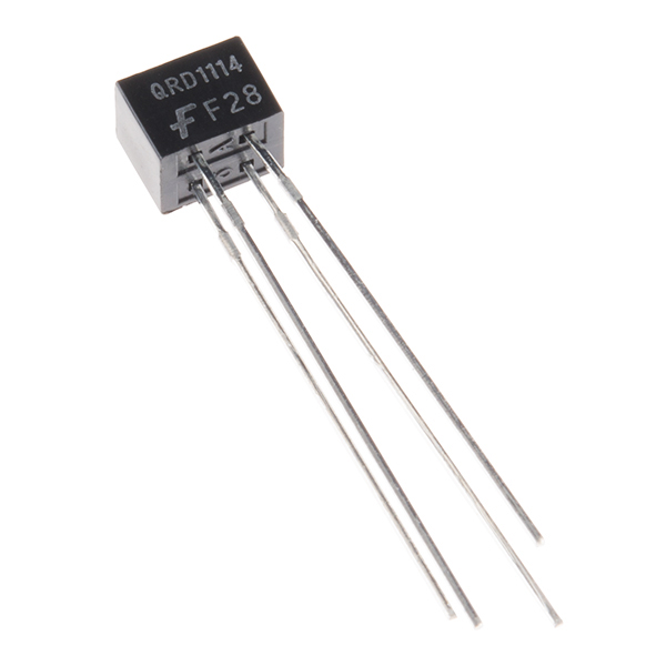
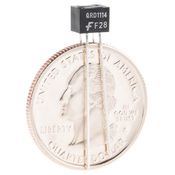
- Optical Detector / Phototransistor - QRD1114

Optical Detector / Phototransistor - QRD1114
This sensor uses an infrared emitted diode combined with an infrared phototransistor to detect the reflected infrared signal. Ideal for sensing black-to-white transitions or can be used to detect nearby objects (.5-1cm).
Optical Detector / Phototransistor - QRD1114 Product Help and Resources
QRD1114 Optical Detector Hookup Guide
May 5, 2016
Use this IR LED/phototransistor fusion to sense objects in close proximity or even the color of a surface!
Core Skill: Electrical Prototyping
If it requires power, you need to know how much, what all the pins do, and how to hook it up. You may need to reference datasheets, schematics, and know the ins and outs of electronics.
Skill Level: Rookie - You may be required to know a bit more about the component, such as orientation, or how to hook it up, in addition to power requirements. You will need to understand polarized components.
See all skill levels
Comments
Looking for answers to technical questions?
We welcome your comments and suggestions below. However, if you are looking for solutions to technical questions please see our Technical Assistance page.
Customer Reviews
4.3 out of 5
Based on 4 ratings:
1 of 1 found this helpful:
Good but not as sensitive as wanted.
The sensor isn't super sensitive, with the recommended resistors it sits around 1020 in ambient lighting, when you put something close to it it will only change 2-10 digits usually. if light is shining on the sensor it will drop down dramatically (500-900) range. This makes it easy to see if something breaks the light going to the sensor. For our project we had it enclosed in a tube & to sense if there is a ball there or not. So we put an LED across from the sensor so if the ball broke the light it would be obvious to the sensor.
Good Product
Good product
works ok when object is very close, a bit flaky with shadows.
I bought these for embedding in a "pinewood derby" race track to detect when the cars pass over the finish line, and it seems to be working well for this after a few tweaks..
I was very worried when prototyping by the fact that the object has to be REALLY close (about half an inch) to reliably "trip". I had to play around quite a bit with how much of a "drop" to treat as a real detection, and how much of a delay, as if I made the drop too big, and moved slowly, it wouldn't register.
Also, this using an infrared detector, it gets a bit flaky in light/shadows. Many times my prototype would "trip" if a shadow inadvertently fell across it, or if a light was shined on it. I ended up having to build a "hood" to try to block as much as possible.
It is working well now that it is mounted in the track under the shelf, will update after the official raceday where we run hundreds of heats.
Thank you Sparkfun.
Better for line following rather than detecting objects
I made some linefollower robots for different competitions and this sensor is really precise. between 0.5cm and 1.2 cm you have a resolution of 800 units out of 1024. This is awesome. For robocup rescue A, this is way better than a qre sensor, and also cheaper.
If I want to sense RPM with this sensor in good control environment (I can paint the surface) and it will be shielded from other IR sources.. How fast an RPM can I detect considering no limit in the MCU?
http://www.flickr.com/photos/jmillerid/414926843/sizes/o/in/set-72157594579056599/
This photo set shows an application that works. I got this running last night.
I'm trying to use this to detect a black stripe on a white rotating disk, with the sensor configured as in the Bildr tutorial. However, with the disc close (1/8-3/6" maybe) to the sensor, there's almost no noticeable difference in the value reported through analogRead for white vs black sections of the disk. With the disk removed (nothing reflecting, value should come from ambient light), it reads around 983. White areas read around 36-38; black around 40-44. I was hoping for a much larger difference. Is the disk too close to the sensor? Is the black ink I'm using too IR-reflective? Something else?
What RyanM said worked for me too, but I used a 10 k ohm resistor instead of the 5.6 k.
For those curious, I've found the best way to get good, repeatable results with this sensor is to set the transistor up as an open collector, with a 10k pull-up. (This means tie the emitter to ground, and measure the output at the collector). Then have a 1k high-side resistor on the IR led, and the difference between white and black reflectors is immense. White brings the signal almost to ground when it's close, and black hardly budges at all. If you have any questions, feel free to reply.
Alright i am making a simple pinball machine..... My question is, can i use one of these to detect the ball falling into the retry position(past the flippers, end of game). Now let me set the context, I read on here that you can separate the emitter and the Photo-transistor , and i got to thinking why would you do that,is that so you can set them up directly across from each other? Think garage door sensor. they will be only inches apart. Now i am asking this because from what i have found it really won't detect a shinny metal ball zipping past it and not many detectors will. Also i'm a mechy, and this is awesome. :) thanks!
I'm getting a blank .pdf for the datasheet. :\
Seems to be working fine here. Maybe try a different browser or right-click and "save link as.." if you are still having troubles with it.
That did the trick, Thanks.
oh bummer -- doesn't work as a sensor for a laser-printed encoder wheel. datasheet seemed to indicate it would (Ic vs. distance) but in by-hand tests with a piece of paper, optimum distance for a black-sharpie-square-on-white-paper seemed to be about .75". it may be that my encoder wheel's marks are too small; 512 of them, 200mm diameter, so the marks are about 1/8" wide. Wheel to sensor distance is 50 - 100 mils. I'll do the physical experiments (focusing tube, 16 segments/circle, etc) but has anyone used this thing for an encoder wheel?
Hello- This works very well for an encoder wheel with laser printed 1/8 marks. I have it about 1/8 inch away with the sensor oriented so that the mark crosses the emmiter and detector at the same time. I have a 220ohm resistor on the LED for 5V, (you could go as low as 100) and a 4.7k pullup resistor on the output. I have output with emmitter to ground, collector to the arduino pin, and 4.7k from the arduino pin to 5V. You can play with the resistor values to change the sensitivity. Also if you need to you can use a 74LS14 to clean up the output or use a 2n2222 to make a darlington pair on the output and increase sensitivity but you should not have to. You may have too many marks or they may be too small, in which case you have to be right against the paper. If you need to be further away make your marks wider. Oh, and it has a 'sunlight filter' but it really works best if you block room light. If you can cover your sense area to keep out light it works much better.
I love this thing, it works great!
thanks for the reply, i forgot to update my experience -- which is more or less as yours. i ended up with a 16 sector wheel, and a crappy 2n3904 amplifier with 10K load. Because i didn't have a schottky device in the drawer, but it needs the hysteresis. Mine's in the dark, spacing is about 3/32". I'm running the LED at recommended current (20mA; 180@5V).
Any ideas as to whether or not this would function as an optical encoder for a custom built out runner brushless motor? The idea being; to completely bypass all processor involvement by running a printed sine wave past the sensor that in turn would send its signal to a MOSFET and then on to the motor, with the voltage controlled via a potentiometer.
certainly not by itself -- i think you mean, generate a sinusoidal voltage by pointing this thing at a printed pattern and having it output an analog sine wave? it's just a transistor; the output is not linear, and wildly more-or-less square-law dependent on distance to paper, paper/ink density, etc. it needs much processing.
(btw, i ended up, of course, pitching my crap amp and installing Schmitt trigger gates and now i get sub-1% accuracy. sometimes laziness does not pay off. :)
(lol, your idea is actually a fairly ancient technique, often called a photoformer, or function generator, to create an arbitrary waveform using an opaque mask (paper, etc) a light source and a detector, one of those being movable as a control input.)
http://rsi.aip.org/resource/1/rsinak/v30/i5/p318_s1?isAuthorized=no
Has anybody used these with a trimpot to adjust the sensitivity? (Not the LED brightness, the phototransistor sensitivity)
Can the collector handle 3v? and what is the max voltage and current for the built-in infrared LED?
The datasheet has this information. The max current through the LED is 50mA. The Vf is 1.7V. You can plug those numbers into a LED calculator to pick the proper resistor for your voltage.
Apparently this part consists of two completely separate components. With the right amount of pressure on the leads, you can pop the 2 parts right out of the packaging, which appears to be a simple piece of plastic. You don't really need it.
I'm working with a Arduino Fio and only have 3.3v available. I tried scaling down the resistors keeping current constant, but the values coming out are erratic. With no interaction, the output oscillates between 0 and ~90 over a 2 - 3 second cycle. If I wave an object infront of it, the values occasionally respond by jumping to 150-200 for a half second but return to the oscillating pattern. I'm an ME not an EE :( Can anyone shed some light on what might be going on and how to accomodate the low source voltage?
This part should work OK at 3.3V, see the schematic for our similar product ROB-09453. It sounds like the detector may be picking up nearby fluorescent lights, which strobe at 60 times per second and can interact this way with your sampling frequency.
10k seems to work a lot better for me. a comparator works very well to get rid of the abient light when set to ~3.5v. ambient light read 1-1.5v and a light surface reads almost 5v.
can this sense lines ans black and white or just distance?
Member105277 - My library is about a year old, but yes, something does look amiss. The arrangement of the labels on the schematic and looks correct compared to the datasheet and my use of them. The collector and anode are on the same side, and the emitter and cathode are on the same side. This is correct. What seems incorrect is that the arrow that designates the emitter ( and that this is an NPN transistor ) is on the collector. It needs to be moved to the emitter. This will make your schematic look incorrect, but the board layout/silkscreen are fine.
Can someone confirm that the Eagle schematic drawing is correct? I believe the Emitter and Collector are backwards (just the names).
Do different light conditions affect when it is used to detect nearby objects in the .5-1 cm range?
This is really sad. I was just using this and out of nowhere it burned. I was supplying it with my netduino's 5V which is constant and safe and the thing just started smoking.
The transmitters forward voltage is 1.7 so you would need to put a limiting resistor to either pins 3 or 4 to bring the voltage down to non harmful level.
Neat little sensor. It's very sensitive and the signal is almost noiseless.
Does anyone know what the response time for these are? It wasnt clear to me from the data sheet.
Rise time 10uS, fall time 50uS. So pretty darn fast.
I made a demo how you can use these to build an array for line following. The array demo can be found at http://www.youtube.com/watch?v=SVdbP_Plils
These are used as digital inputs to an AVR microcontroller (no ADC required). The detector swings from about 150mV to Vcc - 150mV. The detector circuit I used has a 10k resistor in parallel with a 0.1uF capacitor at the collector of the IR detector (output voltage is at the collector). Works very well as long as the sensors are close to the surface used.
Any chance of a future breakout board for an array of five of these? This would be a no-brainer for a line following bot.
I am currently making one from grid PCB and its a little tedious with the 10 resistors, 5 capacitors, power/ gnd rails, and signal pins brought to a 1x7 female header. I will have to design a breakout PCB if I end up making many of these.
I've done some more testing and it can detect up to 3cm if you are lucky.
I'm thinking of using these to detect Kub Cars on a Kub Car track.
Will these be able to detect the cars even if painted dark colours?
I plan to out them on the under side of the track and the cars pass over them with a gap .93cm. That may be too far away.
wizhippo:_
Will these be able to detect the cars even if painted dark colours?_
It's hard for it to detect black, in my testing it starts detecting black at about 1cm. But as always you should test it out yourself.
Was thinking about using these for an arduino segway. What kind of range do these things have?
Using RyanM's schematic (I didn't have a 5.6k so used 6.2k instead), I found it has a range of 0 to 2cm however it's most accurate between .5 and 1cm.
By most accurate I mean that the Analog in range varies a lot. At 2cm, you are up to 950-980 (~1018 is the value when nothing is in front of it).
These look interesting for using with an Arduino - please does anyone have an idea as to how to wire them up?
I've just ordered a pair and will be trying to use them with my arduino, I'll let you know what I figure out. If you understand all that technical mumbo jumbo you could check the document that is linked to in the listing, which is the datasheet.