
PogoBeds: SparkFun Production and Testing
Testbed + Pogopins = Pogobed

Pogo beds 115 to 118
SparkFun has around 1300 products for sale (currently). Out of those 1300 around 1000 products are normal re-sold products like USB cables and other development tools. Just over 300 however, are designed and built right here in Boulder, CO.
Often people on a SparkFun tour are surprised to find out just how many widgets we build in-house! We're just about to build our 250,000 widget. Sounds great, but what people often don't realize is that we test every single unit that is built. How do we do it? Well, our testing procedures and equipment have changed dramatically over the past few years. This tutorial will give you an insider's view into how SparkFun tests all those widgets.
Every product that comes out of production has to be tested to make sure it works. Sometimes we need to verify the output voltages are correct, sometimes we have to make sure some sort of data communication is working.

Above, you can see an example of an old testbed. Nick is using a modified Olimex LPC Dev board to test his HMC compass modules. In order to make a temporary connection to his compass module board, he has to hold it in place on a line of male headers, then apply a slight pressure down to ensure a good connection. Sounds like it would never work, but it does quite well if you have all the interface pins on one side of the board. It actually doesn't take much to create a temporary electrical connection. The problem that we found is that these hacked together test jigs (who were created by surly engineers who were never around) would often wear out or break.
When testing 5-25 units, this method works pretty good. But what do we do if we need to test 400? It becomes really important that the test jig be reliable, and more than anything, be fast! The pogobed has made this much easier, allowing you to push the board down on a set of pogopins. We have started to put a lot of effort and design into test jigs that use pogo pins. Pogopins are these nifty spring loaded pins:
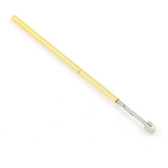
The head of the pin can be compressed downward. It takes very little compression on the pin to create a good electrical contact to a board under test.
Each pogobed is made up of three different PCBs:

A bottom layer (shown above) where the gold part of the pogo pins are soldered to the PCB and includes any required test circuitry. In this case, it's an ATmega168 to do analog to digital conversion and an FTDI Basic Board to convert the serial to USB. Power is gained and regulated through the USB board.

A middle layer (with holes where the pins to poke through).

And a top layer to accurately line the board under test to where the pogo pins stick through the middle layer. Notice the large cut outs around the corners. No PCB is made perfect and internal routing cannot be made perfectly square. These big cut outs allow us to get the board under test in there snugly. The big cut out on the left side is so that we can lift the board out after it has been tested.
 |
 |
 |
 |
 |
 |
Each one of these is custom-designed for one product! Many people believe that creating a good product is all it takes. I believe that's about 30% of the battle. Testing, sourcing, and building to demand is a huge undertaking! Pogo beds solve a major portion of this. They allow us to make temporary connections with the board we'd like to test. We can program and test something very quickly by pressing it down on it's pogo-bed.


The above pogobed is designed for testing the IDG500 Gyro Breakout Board. The bottom layer has an ATmega168 reading the voltages from the gyro and then sending that data over UART on a FTDI basic. Click here for Eagle files and source code.
Test Code
When I hit reset, the ATmega comes up through the FTDI Basic board, and spits out the following text menu:

Text menus rock! It's always a joy for me to see my code actually communicate with the world - whether it's a simple blinking LED or a menu reading out on a terminal window. I am particularly stoked on my "graph" function.
Scrolling Visual Graph Function
Graphing this way is rather lengthy and may look inefficient, but the goal here is to be simple to understand and fast! First, it reads an ADC on one of the Gyro's axis. Then it spits out a line of dashes, followed by the ADC value. The amount of dashes is determined by the value of the ADC. As it continues to spit out more data, it draws a scrolling visual graph on the terminal. When you wiggle the gyro on the pogo bed, it looks something like this:

It's a nice way to visually see that your board is working. Shorts to ground and VCC show up as 'stuck' axis. Problems with component soldering (or missing components) show up as lazy or soft axis. We can also test for certain ADC value thresholds. Click here to see the entire test procedure.
Hanging Around Production

Here we have the testing hardware cabinets. A bit over-exposed, but as you can see, it is very bright in the tech shop. There are now 138 different pieces of test gear! As I cruised through the tech shop with the camera, I ran into a few SparkFun dudes:

Here, we have Nick sitting at one of the test stations. He was testing the HMC compass modules mentioned above. The test code on the HMC compass testbed works a bit differently. Instead of doing A to D conversion, the HMC requires a digital interface. In this case, we simply need to test the board to make sure the IC is responding correctly. A quick 'Hey, are you there' I2C test is enough to make sure the digital interface is working and the IC is functional.

Look who it is! Matt Bolton, our very own Director of Production. I just so happened to run into him as he was putting away one of our most complex testing devices. He is holding what we call the "Coin Cell Pusher".

It sounds silly, but this widdled piece of wood is extremely handy! It helps us easily push coin cell batteries out of their sockets. Even this simple tool has to be kept track of, or else people get really mad when they can't get the batteries out of the test unit.
I also ran into Tony, who was working on some RP-SMA connectors:


Here you can see a very friendly reminder from our IT department: always try a restart. ("Did you restart 3 times?" If you haven't seen the video, Sales Guy vs. Web Dude episode #1 is very funny.) I'd like to send a big shout out to our IT department, they are working really hard to keep us up and running. Thanks guys!

Here, we have Mrs. Pacman. It is a simple little pogobed that allows you to quickly see if your Lilypad Vibe Board is working. Just plug in power to any of the connectors below, and push your board down on the pogobed. If it vibrates, call it good! Our highest score on our Mrs. Pacman (oh yeah, the original model) is by Rob at about 470,000 points. He can basically play the game until it breaks. Nice one Rob. Let your geek shine!

Here we have the MP3 pogobed. Simply power it up, push your board down, and if you hear a tone, it's good to go.


Here we have a slightly more elaborate pogobed. It quickly tests congruencey on a GM862 Eval Board. It runs a little current through all 50-pins (individually) and lights up 50 LEDs. It has two buttons to press, which light up every-other LED. This makes it really easy to check for jumpers and cold connections. This apparatus was designed by test-bed ninja Joel Bartlett. In his written test procedure he calls for "GM862 Pogobed", but it is better known as "Vlad the Impaler".

Here is the Logomatic tester. This is one of our older testbeds, but still works great. Note the copious amounts of hot-glue to hold the wires in place. With the 8 SPDT switches you can ground-out each ADC on the Logomatic to make sure the solder connections are good. It has an LPC Serial Port Boot Loader interface for programming and debugging. Almost a year ago, our very own Pick n' Place operator, Bob, made this beauty.

Here we have one of my first test jigs. Back then (about a year ago), I was still new to Eagle, and thought that hand-wiring a testbed was my best option. This works, but takes a bit of time and wiring experience. Now I've learned how to quickly lay out a board in Eagle, send off the gerbers to BatchPCB and jump on another design. We still use this ziff jig for pre-programming our ATmega DIP chips.

Here is the Barnacle Test Fixture. It uses a IMU 6DOF V4 Controller Board and an LPC programmer to talk to the Barnacles. This little fixture was put together by the designer of the Barnacles, Pete Dokter.

Our hot-air re-work master, Tyler Talmage assembled this jig for testing the Bluetooth Portable Rotary Phone.


This is one of our first attempts at a pogobed. The jig is used to configure bluetooth modules before we solder them onto a board (like the BlueSMiRF). As you can see in the close-up photo, the pogo-pins are soldered into place on the PCB and then the thin red wire is soldered directly to the pogo-pins. This is actually pretty hard to assemble because when you heat up the pogo-pin, it also heats up the solder holding it in place. It comes out looking pretty ugly and sometimes with poor connections. On top is a piece of clear plexi-glass, that was milled out by Casey Haskell, our in-house mechanical engineer. It turns out it is easier to have a PCB made to help line the test board up to the pins, rather than use a CNC machine to mill out plastic. How far we've come!

Here is a battery powered testbed used for testing multiple GPS Micro Minis. With this, we can plug in 9 units at a time, take it outside and ensure that all the modules can get a lock.

And last but not least, the EasyDriver pogo bed. Designed by Joel Bartlett, this jig certainly steals the show. It's got an ATmega168 on the bottom board that talks to the EasyDriver (via pogo pins). It then sends the motor lines (via pogopins) back through the bottom layer and is hard-wired to a stepper motor. The end result... power up, press down and "Yar Flag should be flappin!!"
I'd be happy to post more eagle files if you're interested. Just let me know, and I can share them on BatchPCB. We now sell three varieties of pogopins, which have proven to be very useful for production here at SparkFun. If you've used them in one of your existing projects, or have any new ideas, please post a link below! I am interested to see what else they can be used for.
Great info. Never seen pogo pins before!
Very useful info. Thanks for posting! What tolerance do you use for the cutout on the top board, so the tested board fits snugly (not too loose and not too tight)? Where do you manufacture boards with such unusual cutouts? Do you use different pogopins (head shapes) for making contact with pads versus vias?
Hi there! We now call the top layer the "frame layer" cause that's a little more clear when designing waffle-top testbeds. When we draw the frame layer, we follow these steps:
1) copy the outline dimensions of the board-under-test into your testbed design(frame layer). 2) move the board-under-test outline to the reference layer. 3) draw the frame lines on the dimension layer directly on top of the board-under-test reference lines. At this point you can either draw in the "corner cutouts" as squares or circles. Or you can wait to do it later. 4) make sure all lines (both the reference and dimension) are 0.008 inch wide 5) set your alt to 0.016 inch 6) move the frame dimension lines out one alt click (0.016 inch). We have found with our fab house, this is the correct size gap between board-under-test dimension line and frame dimension line.
Most fab houses don't have a problem with strangely shaped cutouts. One tip though - if you want a space milled out, it's a good idea to include a text object on the dimension layer with the words "ROUTE OUT" in the space you want removed. Otherwise, it can sometimes just come back as a line in the top copper.
Yes, we use pointed for vias, and round for pads. This can help avoid scratching up the test point too much.
Hope this helps, and good luck with your project!
Is the +0.016" tolerance appropriate for routed and sheared PCBs?
Not sure what you mean by "routed" and "sheared" PCBs. Could you explain more?
Usually when we use the term "routed" around here we are talking about a standard PCB with an outer dimension that is milled on a CnC machine with a drill bit. The only other type of PCB division we deal with is when we request a V-score. Is this what you mean by sheared?
In the video when he got bit by the HV on the EL wire driver, it made me think that there should be a better (and safer) method of holding the boards being tested. Check out these toggle clamps for ideas on enhancing your testing of HV enabled boards. Probably not necessary for the smaller and low voltage boards, but anything that has high voltage where you really shouldn't be touching the board while powered, or with lots of pins needing even pressure over the entire board, toggle clamps might be a solution to entertain.
Good presentation. Out of the box thinking at its very best. If all of America had this kind of innovation we could be the land of milk and honey... but it does not. What a pity.
Curious how much this has changed since 2009. Do you still use three-PCB pogobeds for testing?
Yes, we still use 3 PCB pogobeds for simple boards, but we also have some very complex pogobeds that have more than 3.
i know this is kind of old but why not simply use a alligator clip with rubber tip to hold down the board. It will be fast and more secure/steady than your hands..
Just my 2 cents...
Ha -- or DE-STA-CO toggle clamps. :D
Typographical error in the last paragraph.
Whoops, thanks! Fixed.
I like how you used the top two circuit boards. I always use to just use a bland board then sit the test board on top and use a cheap clamping device to hold it down.
I do have to say I am a little disappointed in your production area. No static straps on employees (I am guessing no heel straps) also over top fume extraction. Fume extraction from the top just draws all the harmful vapors right past the operators nose.
This is pretty old and things have changed quite a bit in production now.
I think it would be great if Sparkfun would sell one of these for educational purpose. I would love to get a kit of one of the more simple Pogobeds to learn from building it. Any of them would work but it would probably be best if it was low cost and tests a low cost breakout. Any chance of a Pogobed tutorial kit?
Great tutorial. During my works in Asia I have seen some massive pogo beds and test jigs. The electronics markets usually have several vendors for selling all the parts, handles, hinges, shields, plastics and pins needed to make a test jig. The pogobeds presented here are great examples of test jigs just about anyone can make. Thanks for the tips!
Why don't you put your pins in Barrels so they can be replaced? Also for breadboarding barrels have solder or wrap tails on them.
Hey there,
I've made a pogo test bed to quickly reprogram a tiny board of mine! I looked at your eagle files for your pogo pin fixture bottom board, and it looked like you used 0.040 holes for the pogo pins. I did the same 0.040 holes, however, I couldn't fit the pogo pins into the holes! I had to ream the holes out to allow them to squeeze in. Is this the kind of fit you guys have with pogo pins or should it be free to slide into the solder pad hole?
My boards have parts on both sides and around the edges, so it's not so easy to use a surrounding PCB to hold the target board in place. I've simply placed holes in my target board to slide onto alignment pins soldered in the middle board.
Once I got them in, it worked great!
I'd be happy to post a pic, not sure how though.
Thanks for the great tutorials!
Dan
Ah, fascinating! A company I used to work for also used pogo pins extensively in test fixtures. But, since mechanical engineers designed the fixtures, our approach was a bit different. We machined a plastic plate to match the board under test and inserted the pins in pogo pin receptacles in the plates. Pogo pins do wear out eventually, and using the receptacles makes replacing them faster and easier when you can't readily carry the fixture over to a soldering station.
Pogo pins rock! Why place a huge 0.1" 6 pin ISP header on your 1"x1" sensor board when you can place 6 pads and use pogo pins to program your atmega.
I agree, pogo pins do rock! I've thought about using pads and pogo pins for programming, and we actually do this for the open servo board. For most of our products though, we like to use the 6 pin ISP header so that you (the customer) can re-program it without the need of a special pogobed. Thank for your comment!
It's amazing how much you guys share with us! Cool!