- Home
- Product Categories
- Power Connectors
- XT60 Connectors - Male/Female Pair

XT60 Connectors - Male/Female Pair
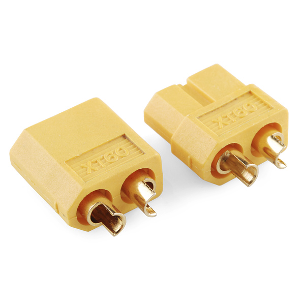
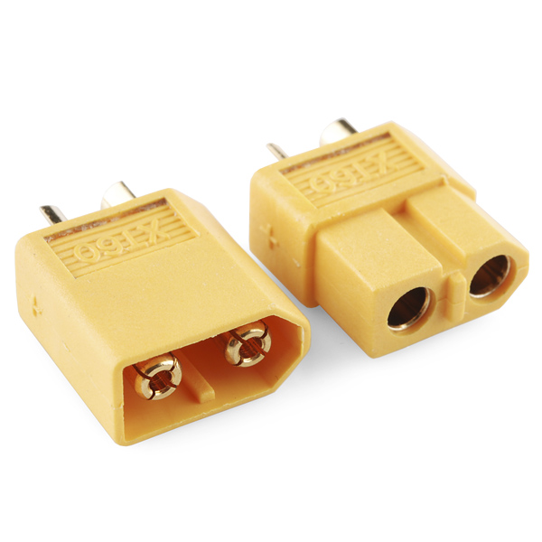
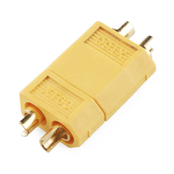
These connectors are made from high-temp nylon with gold-plated spring pins or sockets molded in. The shape of this generic XT60 prevents reverse polarity, and when plugged in the connection is super-solid. Perfect for applications up to 65A continuous draw. Sold in pairs of 1 male and 1 female connector.
XT60 Connectors - Male/Female Pair Product Help and Resources
Secure DIY Garage Door Opener
January 16, 2020
Did you know that most garage doors are at risk of a roll jam attack? Here we make a DIY garage door remote-control system that is much more secure than most commercial-ready products using the latest in ECC cryptography.
Core Skill: Soldering
This skill defines how difficult the soldering is on a particular product. It might be a couple simple solder joints, or require special reflow tools.
Skill Level: Rookie - The number of pins increases, and you will have to determine polarity of components and some of the components might be a bit trickier or close together. You might need solder wick or flux.
See all skill levels
Comments
Looking for answers to technical questions?
We welcome your comments and suggestions below. However, if you are looking for solutions to technical questions please see our Technical Assistance page.
Customer Reviews
3.5 out of 5
Based on 2 ratings:
This is the best power connector on the planet, bar none!!!
Look no further, this is the best power connector on the planet, bar none!!!
For anything below 42 volts that needs a reliable connection, especially when you have low current at startup (processor boot, no motors running just yet), you need a gold plated connector. The 4 point pressure system insures robust, redundant, low ohmic contact for this very thing.
The high current capability insures great performance once the motors kick in!
I've switched over to these 100% on all my projects after trouble with other connectors like the Deans, Andersons, etc.
I was delighted to see the actual drawings of this item. However, there was a dimension left out. Can you reveal the distance between the protruding pins?
Erm, up to and beyond 65A continuous draw? Does that mean it can do 1000A? =)
for an immeasurably small amount of time, probably.
Agreeing on need for pictures with rulers involved, for now I'll just assume they're smaller than a toaster and larger than a grain of rice.
We're working on making our own drawing for these.
...and still working on it - must be some drawing!
And they are up!
I'm making them as we type! I've been at it for two years solid now, but check back tomorrow because they'll be done!
Your mouse must be worn out by now from all that CAD drawing ;), you'd better take a break and go have a beer. Actually I was just curious.
No worries! :)
And very nice drawings they are too! You didn't forget us Metric people :)
Yea I try to keep that in mind. I'm always slowed down when something is only in mm because I have to convert things by punching them into Google.
Well try this great conversion program, it's very cool, quick and useful. It's Win anything, but runs on Wine too apparently. I've used it for years and it's really handy and far quicker to use than others I've tried, and it's small enough that it doesn't get in the way :)
Cool, thanks!
it hopefully will be. oddly enough, there are NO dimensional drawings available for these anywhere. we are still looking for SOME source, but even manufacturers claim they have no dimensions. I can tell you simply that they're about the size of a dime or so. They're just assumed as a 'standard' connector in RC applications, so everyone just takes the size for granted.
LOL, OK, it was only a joke! Sorry if I have a twisted sense of humour :) What would be useful for people though is just a photo with the usual ruler picture beside it, just so they can get a perspective of size. Unfortunately saying it's about the size of a dime is like me telling you it's the size of an Aussie 10c piece, but thanks for trying. By the way, what do you use to put those ruler dimensions in the pictures?
We use Photoshop for rulers.
As for the size, we never really did anything with it because they're very common and pretty standard in RC. But a drawing is actually coming soon.
Thanks for the prompt response :) ...now you better go and have a beer too - Oh and buy Paul one for all his 2 years of slaving over a hot mouse!
Actually, my favorite connector for this kind of application is the Anderson PowerPole line of connectors, which can handle high currents quite easily. Good things about PowerPoles: 1) Easy to crimp, 2) hermaphrodite connector, so you don't have pairing issues, 3) shells in rainbow colors, 4) self-interlocking to make your own multi-conductor connectors. Not so good: 1) Crimping is only easy with the proper crimp tool, 2) not cheap, it costs a little more per contact than these XT60's.
PowerPoles might make a good product for SparkFun to carry. There are crimp pins for various current ratings, many colors of shells, and pins for PCB mounting. The PCB pins and shells in colors other than red and black can be hard to come by in small quantities. Here is a little write up I did for the local robot club:
http://hbrobotics.org/wiki/index.php?title=Anderson_PowerPoles
Can sparkfun offer these as singles, i.e. just a male by itself or just a female by itself (not in pairs)? I seem to always have one sex or the other of various connector types collecting somewhere after the mate goes off elsewhere.
We do not sell these separately, unfortunately.
i like that you're starting to put out male / female inline connector sets, something of a hole in your product line. Now I don't have to order as many parts from Mouser.
You could take a picture with it sitting on a US $0.25 piece. At least anyone worldwide can work it out from that.
To 65 Amps... and beyond!
According to http://wiki.xtronics.com/index.php/Wire-Gauge_Ampacity you would need a 8 AWG wire to carry 65A. A 12 AWG wire max is 41A. Please be careful these are potentially dangerous current values.
For what it's worth, these can sort of fit 10 awg decently. Still not quite ideal for 65A, though. Depends in part how long you use the wire, what kind of casing the wire has, and what you're willing to tolerate in losses.
These xt60s are what I've been using for a long time; they're wonderful.
Certainly there must be a maximum current and maximum voltage rating for these. Does it really need to be “left as an exercise to the reader” to determine the maximum limits?
What is the standard polarization and "direction" for these when using them with a battery pack? I'm assuming the male contacts / female housing is for the load side, and the female contacts/ male housing are for the battery side.
It would be nice for the defacto standard to be mentioned on the product page to simplify this decision for everybody.
Cheers,
- Dean
Everyone has answered your question (and, well, it was a year ago)
But what you ask is precisely one of the benefits of these connectors. Neither side has exposed terminals.
However, with these batteries what looks like the female side is actually considered the male side, by hobbyking standards at least (a common place to buy LiPo batteries.) As such, the side that goes into the other side (which surrounds it) is the one that is considered the battery side piece. Erm, I dont know if I could have been worse at describing it.
But, one side fits into the other side. The side that fits into the other side is the battery side.
I see what you're asking. Traditionally, the female end goes to the battery.
This way the battery won't short if it happens to bump into a piece of metal, which it could easily do (and start a fire!) if the male end was on the battery.
Look at the photo, + and - are molded on the housing.
Ooops, sorry, mis-read your question. Your assumption that "male contacts / female housing is for the load side" makes the most sense from a "don't put a battery pack in your pocket and short it on your car keys" viewpoint.
XT60 connectors are standard sized. Let me see if I can track down a generic datasheet.
At least photo with the rulers to give idea of physical size :)
Datasheet PLEASE!
Datasheet is hard to come by, from what I could find:
Dimensions :
Female side : L 20mm x W 15mm x H 8mm
Male side : L 20mm x W 15mm x H 8mm
Total Length when conneted together : L 33mm
original manufacturer: Amass
what gauge wire do these connectors take? Do they need to be crimped, or are they designed to be soldered to directly?
You will not be able to crimp these.
Make sure you use heat shrink tubing, electrical tape is not a good idea with these.
They can take a 12 gauge wire. You solder the wire to these connectors.