SparkFun AST-CAN485 Dev Board
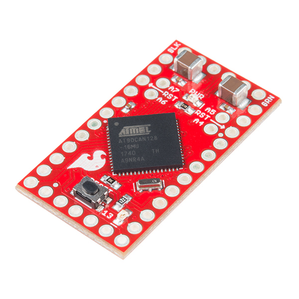
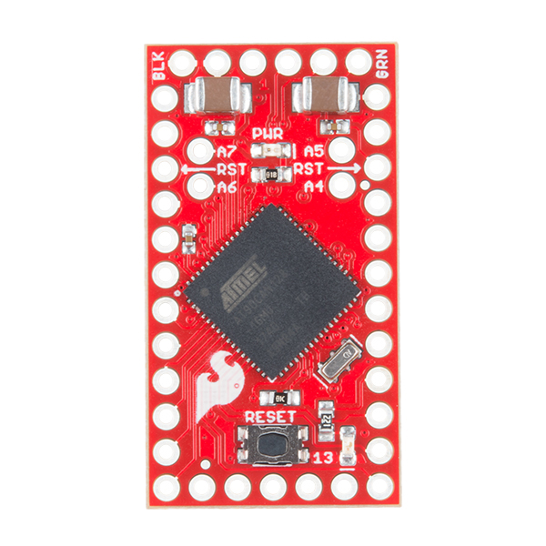
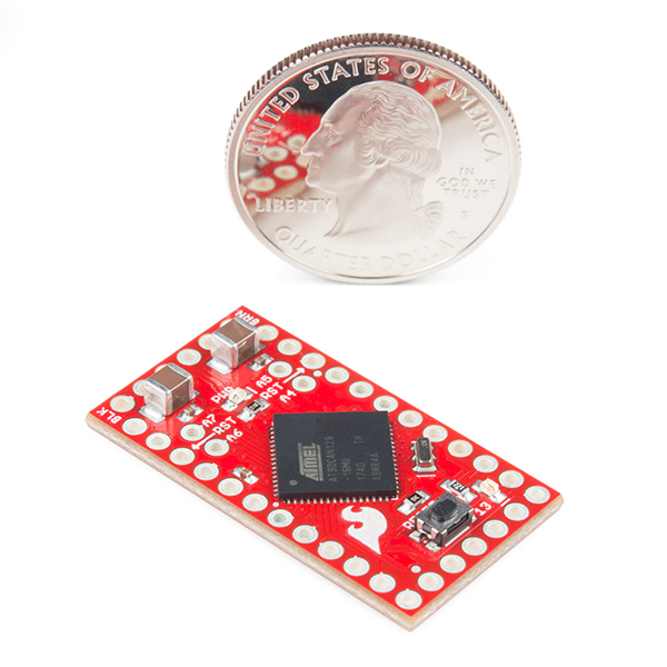
The SparkFun AST-CAN485 Dev Board is a miniature Arduino in the compact form factor of the Pro Mini. In addition to all the usual features that a mini Arduino has, it possesses an onboard CAN (Control Area Network) and RS485 ports, enabling quick and easy interfacing to a multitude of industrial devices. The CAN485 Dev Board bridges the gap between the maker and industrial spaces!
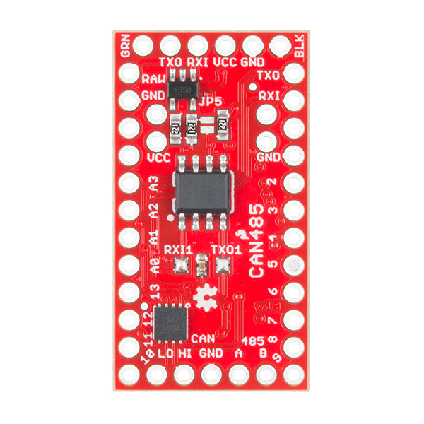
The CAN485 builds on the massively popular Arduino platform and is pin-compatible with the Arduino Pro Mini, giving it a small form factor ideal for embedding in projects. It supports the Arduino IDE and Arduino core libraries and is installed using the Arduino boards manager. Libraries are provided to support the CAN and RS485 ports, making it easy to get started and interface with. Thanks to the onboard CAN and RS485 transceivers, this development board allows for out-of-the-box interfacing to either network.
The SparkFun AST-CAN485 Dev Board is based on the Atmel AT90CAN128 processor. The processor runs at 16MHz, has 128kB or Flash, 4kB of SRAM and features a hardware CAN controller. The CAN485 breaks out commonly used communications ports and pin functions including: I2C, SPI, UARTs, eight analog inputs and six interrupt-enabled pins. Additionally, the AST-CAN485 is equipped with an onboard regulator, allowing for an unregulated input voltage to be supplied on the VIN pin to make the allowable input voltage range 7--16V. Please keep in mind, however, that 7--12V is recommended.
CAN and RS485 form the backbone of many communications protocols with applications in automation, industrial systems, building management, automotive systems, OBDII and many more. With all of these features combined, you have an economical, handy board with a wide array of functions in the palm of your hand!
- Uses the AT90CAN microcontroller
- 16MHz Clock
- 8 analog inputs
- 2 UARTs
- 16 Digital I/Os
- DC Input: 5--16V (150mA Current Max)
- RS485 Transceiver
- CAN Transceiver
- Pro Mini form factor
- Works with Arduino
- Onboard power and D13 LEDs
- Schematic
- Eagle Files
- Hookup Guide
- Datasheets
- CAN Bus
- CAN bus
- CAN 2.0 Specification (superseded by the ISO standard)
- ISO Standard
- CANopen
- DeviceNet
- RS485
- Arduino Board Manager
- AST GitHub Repo
SparkFun AST-CAN485 Dev Board Product Help and Resources
AST-CAN485 I/O Shield (24V) Hookup Guide
February 14, 2019
The AST-CAN485 I/O Shield is an Arduino shield that will allow the user to interface the AST-CAN485 Dev Board with 24V inputs and outputs, which expands its usefulness into industrial systems.
AST-CAN485 Hookup Guide
March 1, 2018
The AST CAN485 is a miniature Arduino in the compact form factor of the ProMini. In addition to all the usual features it has on-board CAN and RS485 ports enabling quick and easy interfacing to a multitude of industrial devices.
Core Skill: Soldering
This skill defines how difficult the soldering is on a particular product. It might be a couple simple solder joints, or require special reflow tools.
Skill Level: Noob - Some basic soldering is required, but it is limited to a just a few pins, basic through-hole soldering, and couple (if any) polarized components. A basic soldering iron is all you should need.
See all skill levels
Core Skill: Programming
If a board needs code or communicates somehow, you're going to need to know how to program or interface with it. The programming skill is all about communication and code.
Skill Level: Rookie - You will need a better fundamental understand of what code is, and how it works. You will be using beginner-level software and development tools like Arduino. You will be dealing directly with code, but numerous examples and libraries are available. Sensors or shields will communicate with serial or TTL.
See all skill levels
Core Skill: Electrical Prototyping
If it requires power, you need to know how much, what all the pins do, and how to hook it up. You may need to reference datasheets, schematics, and know the ins and outs of electronics.
Skill Level: Competent - You will be required to reference a datasheet or schematic to know how to use a component. Your knowledge of a datasheet will only require basic features like power requirements, pinouts, or communications type. Also, you may need a power supply that?s greater than 12V or more than 1A worth of current.
See all skill levels
Comments
Looking for answers to technical questions?
We welcome your comments and suggestions below. However, if you are looking for solutions to technical questions please see our Technical Assistance page.
Customer Reviews
3.7 out of 5
Based on 6 ratings:
1 of 1 found this helpful:
Can transceiver went out
I bought two to primarily use the can transceivers . Once I got all the headers soldered onto both units and applied a good 5v source to the two units I smelled and saw smoke A hole was in one of the board's can transceiver. Use the boards for rs485 now
Hello. Sorry to hear this! It looks like you received a faulty unit. Please contact our technical assistance team and they will be happy to help you with this.
1 of 1 found this helpful:
Meh...
Sadly two of two boards I had ceased to function for different reasons. For one of the boards, it was the CAN transceiver chip that burnt out on contact with an automobile CAN-BUS OBD-2. No, really: it gave off the 'expensive blue smoke of doom.' It was 'bout that time I noticed there were no protection circuits such as dual Zeners to ground to draw off any spikes, and the chip itself is remarkably fragile compared with other CAN transceivers. The other board it was the comms system. Was working when tested prior to soldering on the headers, but not after. Kept reporting a strange vague error at the end of uploading a sketch. Yes, the first board with the burnt out CAN transceiver could be uploaded to OK. Expensive and fragile. Further, I actually want/need access to two CAN busses simultaneously. Now looking at ESP32 with a dual CAN Tx chip that will deal with the harsh reality of the outside world even without protection circuits.
1 of 1 found this helpful:
Simple to Get Simple Solution Up and Running
I purchased three of these units for a CANbus network in my RV (along with a roll of automotive-grade CANbus cable). It was very straightforward to get the example leader/follower programs working successfully (i.e. it took longer to wire up the hardware than to get the s/w running). The library is well documented but only goes so far. The examples really only demonstrate that the h/w is working and give little insight into the "nitty-gritty" real world applications using this technology. Luckily there are lots of sources of on information elsewhere.
nice and small but the reference is missing
I still try to get this board to read my CAN signals but it seams hard to find a proper reference for the CAN library.
Great, small CAN board
This small board has all I need to complete my "Hack my car" Project. In addition to the CAN Interface it also has a large number of GPIOs and the I2C support I need for interfacing a bluetooh module and a DAB radio. The CAN library is also good, as it supports a number of CAN bus speeds.
Bought for use in RS485 filtering of a signal
I have a digital signal that is transmitted via RS485. I needed to transfer this signal over another RS485 channel, but that channel would transmit the RS485 signal then return to floating a short time after the signal was transmitted. So I purchased 2 AST-CAN485 boards and a couple of RS485 transceiver breakout boards. I programmed the AST-CAN485s to receive/send the digital signal via the additional transceivers. I set each board identity via EEPROM. I then wrote a program that would send a byte from one board to another via RS485 and USART at 1megabaud. When all was said and done I created a digital signal transport over RS485 that added 30 microseconds latency. I was shooting for 50 microseconds.
This board has done everything I asked of it without complaint. It just works and works well. If I ever need another RS485 device or CAN device this will be a board I reach for to fill that need.
Thanks for making it available!


For RS485, please note that the A/B markings on the PCB and in the datasheet corresponds to the transceiver A/B notation, which is the opposite of the RS485 standard A/B notation. In other words, "A" on the PCB is actually "B" and vice versa.
I can't make external interrupts work. None of pins are responding. Same sketch works on Uno (on pin 2). Any ideas?
EDIT: It looks like Arduino functions manipulate wrong bits in wrong registers in attachInterrupt(). Directly setting EICRA and EIMSK registers works and it does support CHANGE interrupts.
I almost completed a project with three of these boards when I started to run into problems uploading code. I decided to reinstall the bootload so I connected an AVR Pocket Programmer and entered a commend line avrdude -c usbtiny -p c128 -F I am getting back "avrdude: Device signature = 0x000000" (not "ox1E9781" as expected for the AT90CAN128 I have checked the connections probably a dozen times.. based on the pin outs shown for the programmer and CAN485. Are my units toast or is there something else I can try?
Hi there, it sounds like you are looking for technical assistance. Please use the link in the banner above, to get started with posting a topic in our forums. Our technical support team will do their best to assist you.
I was intending to use this for interfacing with a high speed RS485 bus (2Mbps) but it looks like the board can't handle that. The output waveform on the RS485 chip is al wonky. Apart from that, this is a great board!
Is it possible to use this board and have it wake on CAN activity? I'm looking for something that can be left connected to a vehicle battery feed, wake up when there is CAN activity and run some code / transmit some CAN messages, then sleep when the vehicle CAN bus goes dormant again.
I'm not sure if there's a CAN bus interrupt to wake the micro, but you can always use the OBD-II port (if your car is newer than 1996) and use the accessory 12V power (which is only on when the car is on) and regulate the voltage down to 5V.
Yes, an accy circuit would be ideal but where I have to package and connect this thing there are only CAN lines and B+/ground. So unless there is a wake on CAN I would not be able to put this in low power mode, hence risking battery drain.
This is ALMOST exactly what I need except I REALLY need a micro-usb port for programming? Is there a way to attach a usb port to this? I need the RS485 for its long distance ability.
To program it, you’ll need a USB to UART Bridge which has a USB micro B connector on it.
link to github is this https://github.com/Atlantis-Specialist-Technologies/CAN485
and not the one with admin in it
Sorry about that, we had to work with AST to turn on certain repositories. It is live now. =)
Link to the AT90CAN128 datasheet is broken.
Sorry about that, we had to work with AST to turn it on certain repositories. It is live now. =)
yes here it is http://ww1.microchip.com/downloads/en/DeviceDoc/doc7679.pdf