MIKROE AM/FM Click
MIKROE AM/FM Click is a RADIO RECEIVER Click board™ that can be used to listen to music from the AM and FM radio bands.
Product Overview
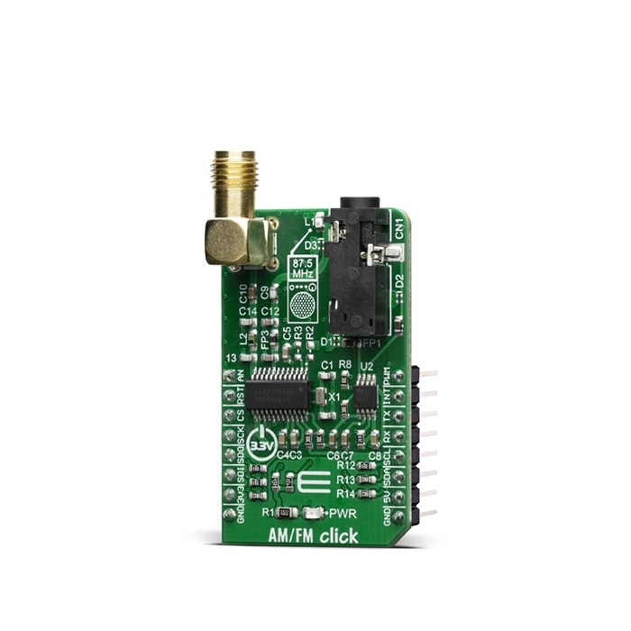
MIKROE AM/FM Click is a RADIO RECEIVER Click board™ that can be used to listen to music from the AM and FM radio bands. One of the advantages of this versatile FM broadcast stereo transmitter IC is that it is very easy to work with it, which makes it an ideal solution for using it in cellular phones, MP3 players, portable media players, wireless speakers, personal computers and any other applications, where the radio receiver is needed.
The AM/FM Click is based on the Si4731 IC - digital CMOS AM/FM radio receiver IC integrates the complete broadcast tuner and receiver function from antenna input to digital audio output, from Silicon Labs. The audio signal from the output of the Si4731 is brought to a mini 3.5 female jack on board, over the LM4910 - an output oapacitor-less stereo 35mW headphone amplifier, from Texas Instruments. That way, it is ensured that user can plug in the headphones directly into the Click board™, without the need for any external amplifier.
The Si4731 IC The device leverages the Silicon Labs broadcast proven digital low-IF architecture, enabling a cost-effective, digital audio platform for consumer electronic applications with high TDMA noise immunity, superior radio performance, and high fidelity audio power amplification. Audio signal is processed to have the optimal dynamic qualities. The integrated DSP also takes care of the stereo MPX encoding and FM modulation of the signal. The low level digital intermediate frequency (IF) signal is then filtered out and sent to the outputs, that are is amplified, filtered, and digitized with high resolution analog-to-digital converters (ADCs). This advanced architecture allows the Si4731- to perform channel selection, FM demodulation, and stereo audio processing to achieve superior performance compared to traditional analog architectures.
The Click is designed for communication over the I2C/2-wire control interface. When selecting 2-wire mode, SCLK pin should stay at a HIGH logic level during the rising edge on the RST pin, and stay HIGH until after the first start condition. Also, a start condition must not occur within 300nS before the rising edge on the RST pin. The 2-wire bus mode uses only the SCL and SDA pins for communication.
The Si4731 IC has the capability of the received signal measurement. The antenna which is used to broadcast the signal can also be used to accept the incoming signal, sent by the receiving device. Although it can be used both to receive and transmit signal, the antenna can't operate in both modes simultaneously. This feature can be useful when calibrating the transmission power of the click board.
This Click Board™ is designed to be operated only with 3.3V logic level. A proper logic voltage level conversion should be performed before the Click board™ is used with MCUs with logic levels of 5V.


Features & Specs
- Interface: GPIO, I2C
- Compatibility: mikroBUS™
- Dimensions: 42.9 x 25.4mm
- Input Voltage: 3.3V, 5V
- Ambient Temperature: -20°C to 85°C
- FM Band Support: Min. 64MHz, Max. 108MHz
- AM Band Support: Min. 2.3MHz, Max. 26.1MHz
- SNR: Min. 53dB, Typ. 58dB
- THD: 0.5%
Documentation
Customer Reviews

Stock and Customer Discounts
Available Discounts
- $47.45 | 25+ units
- $44.96 | 100+ units