MIKROE AC Current Click
This board is a device that is able to measure the alternating current running through the conductor, using the so-called non-invasive current sensor.
Product Overview
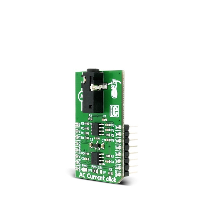
MIKROE AC Current Click is a device that is able to measure the alternating current (AC) running through the conductor, using the so-called non-invasive current sensor. The non-invasive sensor works by utilizing the electromagnetic induction phenomenon, similar to a transformer. The primary coil does not exist though, the electromagnetic field is generated by the AC Current running through the cable which is measured. The core of the sensing probe is split, allowing it to clamp on the current conducting cable. Since the sensor does not influence the measurement circuitry in any way while being galvanically isolated at the same time, it is an ideal solution to measure current running through mains, or similar high voltage installations.
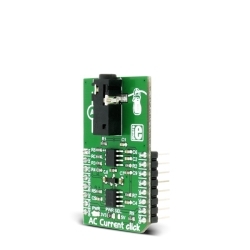
The Click board™ comes equipped with the 3.5mm jack connector which is used to attach the sensing probe. The sensor input is filtered and amplified so that the readings can stay reliable and protected against EMI and radio-interferences. The low-noise 12-bit SAR A/D converter (ADC) converts the sensor voltage, providing conversion data via the industry-standard SPI interface. Besides the onboard A/D converter, there is an analog signal path available to the users, allowing the Click board™ to fit into various usage scenarios. Featuring a high precision ADC and a low noise, rail to rail dual operational amplifier, designed to work with the contactless non-invasive current sensor, AC Current click is an ideal solution for measuring AC Current through mains and other cables with otherwise dangerous voltages, current consumption monitoring, and similar applications.
AC Current Click is equipped with the MCP3201, a 12bit SAR analog-to-digital converter (ADC) with SPI interface, from Microchip. The reference voltage for the conversion is 2.048V, and it is provided by the MCP1501, a high-precision, buffered voltage reference IC, also from Microchip. It is used to sample the input voltage, generated by the contactless, non-invasive current sensor, attached to the 3.5mm jack connector.
As already mentioned, the sensor output voltage is a result of the electromagnetic induction of the magnetic field generated by the cable, through which the AC current runs. The split core of the sensor can be clamped over the cable, providing a closed path for the magnetic flux through the core that way. This will result in generating the voltage in the secondary coil within the sensor. This generated voltage depends on the sensor type and the maximum current it is supposed to measure. AC Current click allows measuring up to 10 A / 1 V, using a sensor that outputs 1 V for the full-scale reading of 10 A. Note that only the AC current can be measured, since the DC current does not have the ability to generate the alternating magnetic field, so the sensor can be used only for the AC current measurement.
The voltage at the input is filtered by the RC filter in order to prevent any additional EMI influences or radio-interferences. The signal is then amplified by the MCP607, a rail-to-rail operational amplifier with a very low offset voltage and biasing current. This allows a minimal distortion of the input. The amplification ratio (G) is calculated by using the formula for the non-inverting operational amplifier configuration: G = 1 + R4 / R3. Knowing the maximum voltage of the sensor (for 10A current), the reference voltage of 2.048V for the ADC and the gain factor of the op-amp, it is easy to calculate the value for the measured current. The Click board™ comes with the library functions that do all the necessary calculations, providing a simple and quick solution for the application development. A user can also easily develop his own methods and functions by utilizing the existing ones if some other sensor with different nominal values is used. However, this Click board™ also comes as the part of the AC Current click - bundle, which also contains the current measuring sensor, calibrated and well suited to work with the AC Current click (10A - 1V).
Besides the onboard ADC, it is possible to use an external converter, by using the AN pin of the mikroBUS™. The preconditioned voltage from the first (non-inverting) operational amplifier is routed to both the onboard ADC and another op-amp, which acts as the buffer with unity gain. It is used to provide a buffered analog voltage at the AN pin, which can be used externally, bypassing the onboard ADC. The MCP607 consists of two integrated op-amps so the same IC is used both for the input pre-conditioning and the output buffer.
The Click board™ can use both 3.3V and 5V as the power supply, so it is able to directly interface with both 3.3V and 5V MCUs. To select the desired operating voltage, it is enough to switch the onboard SMD jumper, labeled as the PWR SEL.
Please note that the product described on this page does not include the non-invasive current measurement sensor.
Note that although the Click board™ is meant to be used for measuring current without making any contact, by using galvanically isolated sensor over an isolated cable, a special care should always be taken when working with dangerous and harmful voltages. Any operation which involves high voltage should be performed by trained personnel.


Features & Specs
- Interface: Analog, SPI
- Compatibility: mikroBUS™
- Dimensions: 42.9 x 25.4mm
- Input Voltage: 3.3V or 5V
Documentation
Customer Reviews
Stock and Customer Discounts
Available Discounts
- $14.20 | 25+ units
- $13.46 | 100+ units