
MIKROE Stepper 16 Click
MIKROE Stepper 16 Click is a compact add-on board that contains a micro-stepping stepper motor driver.
Product Overview
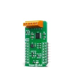
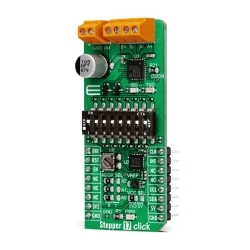
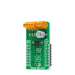
MIKROE Stepper 16 Click is a compact add-on board that contains a micro-stepping stepper motor driver. This board features the NCV70517, an SPI and I/O configurable motor driver for bipolar stepper motors from ON Semiconductor. The NCV70517 contains a current−translation table and takes the next micro−step depending on the clock signal on the NXT input pin and the status of the DIR pin. It also provides an error message if an electrical error, an undervoltage, or an elevated junction temperature is detected. This Click board™ is fully compatible with the automotive voltage requirements and ideally suited for general−purpose stepper motor applications in the automotive, industrial, and applications with fluctuating battery supplies.
Stepper 16 Click is supported by a mikroSDK compliant library, which includes functions that simplify software development.
Stepper 16 Click as its foundation uses the NCV70517, an integrated motor-driver solution for bipolar stepper motors with integrated current sense and current regulation from ON Semiconductor. Two H−bridges are integrated to drive a bipolar stepper motor with a PWM current control loop with on-chip current sensing implemented for each H−bridge. It provides complete output protection, overcurrent protection, and thermal warning and shutdown, alongside with proprietary PWM algorithm used for reliable, current control allowing automatic selection of fast and slow decay.
The NCV70517 communicates with MCU using the standard SPI serial interface with a maximum frequency of 10MHz. One of five possible stepping modes is selectable through bits of the SPI registers. After Power−On or hard reset, the coil−current translator, which translates consecutive steps into corresponding currents in both motor coils for a given step mode, is set to the default to 1/16 micro−stepping at position ‘8’. Besides the micro−step modes, full step mode is implemented, which always activates only one coil.
The direction of rotation is selected by input pin DIR routed to the RST pin of the mikroBUS™ socket and its polarity bit DIRP, which allows changing the direction of rotation through only SPI commands instead of the dedicated input pin. Besides, it also takes the next micro−step depending on the clock signal on the NXT input pin routed to the PWM pin of the mikroBUS™ socket and provides an error message on the ERR pin routed to the INT pin of the mikroBUS™ socket if an electrical error, an undervoltage, or an elevated junction temperature is detected.
This Click board™ supports an external power supply for the motor, which can be connected to the input terminal labeled as VEXT and should be within the range of 6V to 29V, while the stepper motor coils can be connected to the terminals labeled as XP, XN, YP, and YN.
This Click board™ can be operated only with a 3.3V logic voltage level. Therefore, the board must perform appropriate logic voltage level conversion before using MCUs with different logic levels. However, the Click board™ comes equipped with a library containing functions and an example code that can be used, as a reference, for further development.

Features & Specs
- Interface: GPIO, SPI
- Compatibility: mikroBUS™
- Dimensions: 42.9 x 25.4mm
- Input Voltage: 3.3V, External
- Supply Voltage VCC: 3.3V
- External Supply Voltage VEXT: Min. 6V, Max. 29V
- Maximum Output Current (Normal Operation): 800mA
- Step Resolution: Min. 1 steps, Max. 1/16 steps
- Operating Temperature Range: Min. -40°C, Typ. +25°C, Max. +145°C
Documentation
Customer Reviews
Stock and Customer Discounts
Available Discounts
- $19.90 | 25+ units
- $18.86 | 100+ units