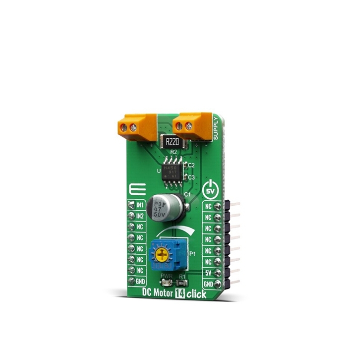
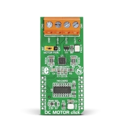
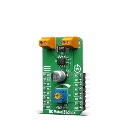
MIKROE DC Motor 14 Click
DC MOTOR 14 Click is a PWM chopper type brushed DC motor driver, labeled as TB67H450FNG.
Product Overview
DC MOTOR 14 Click is a PWM chopper type brushed DC motor driver, labeled as TB67H450FNG. This IC includes one channel of motor output block, using a wide range of supply voltages, while delivering reasonably high current to the connected DC motors. Low ON-resistance MOSFETs and a PWM control help the TB67H450FNG exhibit lower heat generation thus efficient motor drive. Furthermore, the TB67H450FNG has two inputs, IN1 and IN2, which allow for selection of the four operation modes; forward (clockwise), reverse (counter-clockwise), short brake, and stop modes.
The Click board™ is supported by the mikroSDK compliant library, which includes functions that simplify software development.
The main component of DC MOTOR 14 Click is the TB67H450FNG, a PWM chopper-type brushed DC motor driver, produced by Toshiba. This IC uses a proprietary BiCD manufacturing process, allowing this IC to be powered by a wide range of supply voltages, from 4.5 up to 44V. Due to a very low ON resistance of the MOSFETs, it can theoretically deliver up to 3.5A of current to the connected load. However, many external parameters affect both the maximum voltage and the current specifications, especially when the connected load is of a complex nature, such as the DC motor. In using TB67H450FNG, the voltage should be applied to the pins of VM and VREF. The absolute maximum rating of VM supply voltage is 50V (no active). The usage range is 4.5 to 44V. The absolute maximum rating of VREF supply voltage is 5V. The usage range is 0 to 4V.
There are no special procedures of inputting a power supply and shutdown because the TB67H450FNG incorporates the under voltage lockout (UVLO). However, under the unstable state of inputting the power supply (VM) and shutdown (transient area), setting the motor operation to OFF state is recommended. After the power supply is in the stable state, the motor should be operated by switching the input signal.The absolute maximum rating of motor output current is 3.5A. Its operating range is 3A or less. The maximum current of the actual usage is limited depending on the usage conditions (the ambient temperature, the wiring pattern of the board, the radiation path, and the exciting design). Configure the most appropriate current value after calculating the heat and evaluating the board under the operating environment.
When the logic signal is input under the condition that the voltage of VM is not supplied, the electromotive force by an input signal is not generated. However, configure the input signal low level before the power supply is applied by referring to the detailed description in datasheet (“1.2 Power Supply Sequence”).
A speed of the motor can be controlled by Inputting PWM signal to pins IN1 and IN2, and operating them with PWM control.When both IN1 and IN2 pins are set to L for 1 ms (typ.) or more, the operation mode enters into the standby mode. When IN1 or IN2 is set to H, the mode returns from the standby mode, and enters to the operation mode.
When the constant current function is disabled, RS pin should be connected to GND, and the voltage of 1 to 5V should be applied to VREF pin. Maximum 30 μs are required for the return time from the standby release. The OUT1 and OUT2 outputs operate after 30 μs (max) from the standby release.
In this product, a constant current threshold is set by the current detection resistor between RS and GND, and VREF input voltage. When the constant current function is disabled, RS pin should be connected to GND, and the voltage of 1 to 5V should be applied to VREF pin. When the output current reaches the threshold due to forward rotation and reverse rotation, the constant current control is performed in Mixed Decay mode. In case of the constant current control, the OFF time (toff) is fixed to 25 μs (typ.) to determine the pulse width of the current (current pulsating flow). The percentage of Mixed Decay Mode is as follows; Fast Mode: 50% to Slow Mode: 50%. If the output current is zero-detected in Fast Mode, the outputs are in High impedance.
When the junction temperature of the IC reaches the specified value, the internal detection circuit (TSD) operates to turn off the output block. It has a dead band time to prevent the IC from malfunction, which is caused by switching and so on. Since the temperature has a hysteresis range, when the junction temperature falls to the return temperature, the operation returns automatically to the normal operation.
The TSD is triggered when the device is over heated irregularly. Make sure not to use the TSD function aggressively. When the IC detects an over current, the internal circuit turns off the output block. It has a dead band time to avoid ISD misdetection, which may be triggered by external noise. The under voltage detection circuit operates when the applied voltage of VM pin falls 3.8V (typ.) or less. All output power transistors are turned off. The UVLO operation is released when the voltage applied to VM pin rises 4.0V (typ.) or more.
Although the TB67H450FNG IC requires an external PSU, The Click board™ can operate with 5V MCUs only. The current detection resistor (R2) installed on Click is 0.51 ohm and set for range from 0 to 1.5A. If it’s needed range from 1.5 to 3A, that can be achieved by replacing it with 0.22 ohm resistor. It is ready to be used as soon as it is inserted into a mikroBUS™ socket of the development system.

Features & Specs
- Interface: GPIO
- Compatibility: mikroBUS™
- Dimensions: 42.9 x 25.4mm
- Input Voltage: 5V
- Supply Voltage: Min. 4.5V, Typ. 5V, Max. 5.5V
- VM Power Supply: Min. 4.5V, Max. 45.0V
- Maximum Output Current: Min. 0A, Max. 2A
- Operating Temperature Range: Min. -40°C, Max. 85°C
- Logic input (VIN(L)): Min. 0V, Max. 0.8V
- Logic input (VIN(H)): Min. 2V, Typ. 5V, Max. 5.5V
- VREF: Min. 0V, Max. 4V
- Power dissipation: 2.85W
Documentation
Customer Reviews
Stock and Customer Discounts
Available Discounts
- $14.20 | 25+ units
- $13.46 | 100+ units