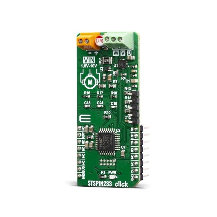
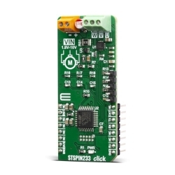
MIKROE STSPIN233 Click
STSPIN233 Click is a complete solution for a 3-phase integrated motor driver, based on the STSPIN233, Low voltage 3-phase integrated motor driver.
Product Overview
STSPIN233 Click is a complete solution for a 3-phase integrated motor driver, based on the STSPIN233, Low voltage 3-phase integrated motor driver. It is optimized for battery-powered, low voltage motor driving applications, featuring the lowest standby current available on the market (max 80 nA). The STSPIN233 is a high-efficiency motor driver, featuring low ON resistance MOSFETs as the output stage, and extremely low leakage current (max 1µA). Its output stage implements the PWM current control with fixed OFF time, along with a full set of protection features. The device can be used with the step motor voltage ranging from 1.8V to 10V, and current up to 1.3A per bridge.
STSPIN233 Click is supported by a mikroSDK compliant library, which includes functions that simplify software development.
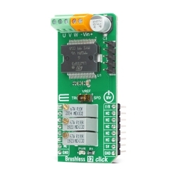
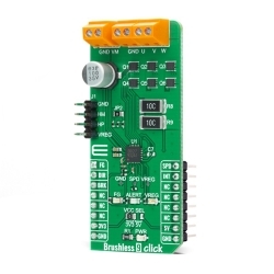
This Click board™ is optimized for driving brushless motors in portable applications. Therefore, the STSPIN233 from STMicroelectronics contains three independent H-Bridges, and each of them controls one phase of the brushless motor. These integrated H-Bridges are very efficient - with ON resistance of approximately 400mΩ (HS+LS) across each bridge. These features make STSPIN233 Click perfectly suited for rapid development of various battery-powered stepper motor applications, including toys, printers, mechatronics, drones, robotics-related applications, etc.
Besides the brushless driver IC, this Click board™ also has STM32F031K6T6 MCU onboard, which serves as a “brain” of the STSPIN233 Click. It comes with a preloaded firmware, which is programmed to take control of the motor driver. It reads the current motor status and signals from an optional rotary encoder, calculates values of desired and real motor status in real time and makes necessary corrections to the motor driver. The motor can be controlled by using these pins: RST, INT, and UART pins – RX and TX. That way, very reliable brushless motor driver is achieved.
The RST pin of the STSPIN233 Click is used to set both bridge outputs in HIGH-Z mod, disconnecting the power supply from the H-Bridges. This pin allows lower average power consumption as no current can flow from the power supply to the motor. This pin is routed to the RST pin of the mikroBUS™.
The INT pin has a double purpose: when set to a high logic level, it acts as a chip enable, allowing the device to operate. In the case of a fault condition on the IC, it will be asserted to a LOW logic level, acting as an interrupt pin. After a timeout period defined by the external capacitor and resistor values, a restart attempt will be made. This pin is routed to both INT pin of the mikroBUS™, allowing the host MCU to use both functions. The mentioned pin is labeled as FLT on the Click board™, respectively.
The motor power supply can be connected to the input terminal labeled as VIN and should be within the range of 1.8V to 10V. Brushless motor coils can be connected to the terminals labeled as U, V, and W. The Click board™ requires an external power supply for the motor in order to work. However, it also requires 3.3V from the mikroBUS™ rail.

Features & Specs
- Interface: GPIO, UART
- Compatibility: mikroBUS™
- Dimensions: 57.15 x 25.4mm
- Input Voltage: 3.3V, 5V
- Output current: Min. 0A, Max. 1.3A
- Input Voltage: Min. 1.8V, Max. 10V
Customer Reviews
Stock and Customer Discounts
Available Discounts
- $16.10 | 25+ units
- $15.26 | 100+ units