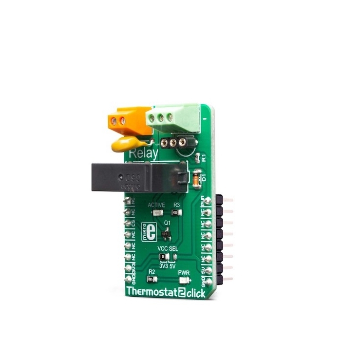
MIKROE Thermostat 2 Click
Thermostat 2 Click board™ is designed without the main IC; it allows an externally connected thermal sensor to be used, instead.
Product Overview
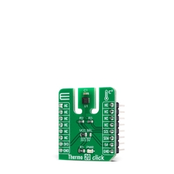
Thermostat 2 Click is a general-purpose thermostat Click board™ designed to be used with any temperature sensor based on the DS1820 sensor design: 3-pin package with 1-Wire® communication interface. The Click board™ is equipped with a 3-pole terminal and a 3-pin female socket. DS1820 (or compatible) sensor can be connected either over the terminal or can be installed directly into the socket. The Click board™ also contains a high-quality relay from Omron, that can be used to open or close an electric circuit. Despite its small size, it can be used with voltage up to 30VDC/220AC and current up to 5A.
Thermostat 2 Click is supported by a mikroSDK compliant library, which includes functions that simplify software development.
The Click board™ is equipped with all the necessary elements, required to provide a reliable operation: it has a varistor across the relay output contacts, preventing excessive voltage transients, it has a flyback diode for the backEMF generated within the relay coil, and a durable mechanical relay, that can withstand up to 20,000,000 mechanical cycles (no load connected). These features allow Thermostat 2 Click to be used for a wide range of applications that have to be thermally controlled: various home appliances, air conditioners, cooling fans, small heaters, etc.
Note: The Click board™ is to be used by trained personnel only while the high voltage is applied. A special care should be taken when working with hazardous voltage levels.
Thermostat 2 Click board™ is designed without the main IC; it allows an externally connected thermal sensor to be used, instead. It can be interfaced with the DS1820 compatible sensor which uses 1-Wire® communication. The Click board™ is equipped with a 3-pin female socket, which can be used to install the DS1820 compatible sensor in TO-92 casing, onboard. There is also a 3-pole screw terminal, that can be used if the sensor needs to be installed on a remote location, i.e. onto a heating component. The screw-terminal shares its lines with the socket.
The 1-Wire® communication with the host MCU is performed over the PWM pin of the mikroBUS™. Depending on the temperature information obtained over the 1-Wire® interface, the host MCU can take the necessary action: it can either open or close contacts of the relay.
The Click board™ uses the G6D series PCB power relay, from Omron. This quality relay can withstand an amazingly large number of mechanical cycles, with no load connected. However, when there is a significant load connected at its output, micro-electric arcs cause the contacts to wear over time. With the maximum load current of 5A, it can sustain up to 70,000 cycles. Its contacts are made of silver alloy, yielding exceptional ON resistance of only 100mΩ (max).
The relay is activated by a magnetic field, generated in a built-in coil on the low-voltage side. The coil is activated by the host MCU. The voltage for the coil activation is 5V, while the current through the coil is 40mA. The MCU is not able to drive the coil directly, therefore an NPN transistor had to be added. Its base is controlled by the host MCU, allowing the coil to drain enough current from the 5V mikroBUS™ power rail. The base of the transistor is routed to the CS pin of the Click board™. The transistor packs two biasing resistors in the same casing, so it can be directly used on the MCU pin, without external biasing resistors. A red color LED, labeled as ACTIVE is used to indicate that the transistor is in an open state and that the current is running through the relay coil.
When the current through a coil (or any other inductor) is suddenly changed, the backEMF will be generated, opposing the changes of the current. This can sometimes lead to damage to the control circuit: in this case, the transistor will become inversely polarized. To prevent this from happening, a flyback diode is added across the coil. During the normal operation, this diode does not conduct any current. However, when the coil is switched OFF, the inverse polarization will cause the current to pass through this diode with minimum resistance. This prevents inverse (flyback) voltage from building up, so the transistor remains safe.
Contacts at the output may be connected to a higher voltage and larger current may run through. To prevent high voltage transients in this case, a flyback diode is not a viable option. Therefore, Thermostat 2 Click uses a varistor (VDR). This component rapidly drops its resistance as the voltage rises above its rated clamping voltage. The excessive voltage transient will pass through the VDR since it will become a current path with the least resistance. During the normal operation, while the voltage stays below the rated clamping voltage, VDR has a very high resistance, so the current runs through the electrical circuit, instead.
The operating voltage of the Click board™ can be selected by the VCC SEL jumper. This jumper allows selecting either 3.3V or 5V from the mikroBUS™. The selected voltage will be applied to the VCC pin of the connected DS1820 sensor.


Features & Specs
- Interface: 1-Wire, GPIO
- Compatibility: mikroBUS™
- Dimensions: 42.9 x 25.4mm
- Input Voltage: 3.3V or 5V
Documentation
Customer Reviews

Stock and Customer Discounts
Available Discounts
- $14.20 | 25+ units
- $13.46 | 100+ units