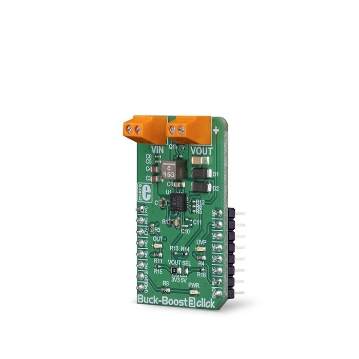
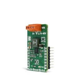
MIKROE Buck-Boost 3 Click
The Buck-Boost 3 Click is based on the ISL85403, a 2.5A regulator with the integrated high-side MOSFET and a low-side driver, by Renesas.
Product Overview
The Buck-Boost 3 Click is a voltage converter/regulator, which is able to provide a regulated voltage of 3.3V or 5V on the output, even when the input voltage drops under 3V. This is possible thanks to the ISL85403, a specialized buck-boost voltage converter IC which features an integrated high-side MOSFET and a low-side driver, that can be used to drive an external MOSFET. Buck-Boost 3 Click perfectly suited to provide power with regulated voltage for embedded applications, points of load, or to be used as the battery voltage regulator, or in similar general-purpose power applications that require regulated 3.3V or 5V power supply.
This device is capable of providing reasonably high current on the output. The frequency of the internal PWM oscillator is 500kHz, which ensures an optimal efficiency-to-size ratio. Buck-Boost 3 Click offers a very tight output voltage regulation, reliable overcurrent protection, it allows a wide voltage range on the input terminal and can operate in both PWM/PFM modes, allowing optimized efficiency for the connected load.
Featuring both buck and boost functionality on one device, while maintaining an accurate voltage at the output, even with heavier loads, this Click board™ can be used to provide continuous power in cases when the input voltage fluctuates a lot, in the range from 2.5V up to 35V.
The Buck-Boost 3 Click is based on the ISL85403, a 2.5A regulator with the integrated high-side MOSFET and a low-side driver, by Renesas, allowing it to be used in different topologies. Buck-Boost 3 Click uses the single inductor buck-boost topology, allowing it to maintain the selected 3.3V or 5V on the output, regardless of the input voltage. The input voltage can vary between about 2.5V and 35V. This makes the Click board™ suitable to be used as the battery power regulator, for example, compensating for the voltage drop, while maintaining the constant voltage at the output, necessary for the embedded system.
The ISL85403 offers two modes of operation: PWM and PFM. These modes are switched automatically depending on the current through the MOSFET, ensuring an optimal efficiency for both light and heavier loads at the output. The PFM (Pulse Frequency Modulation) mode allows the ISL85403 to be more efficient when there is a light load connected at the output. In this case, the frequency of the PWM oscillator can be dramatically reduced since the stored inductor energy is depleted much slower by the connected load. Although more efficient for light loads, the PFM mode results in a slightly higher output voltage ripple. This makes the PFM mode well suited for situations when the connected device enters the hibernation or sleep mode. Buck-Boost 3 Click has a resistor which sets the device to operate in PWM mode until the current through the MOSFET drops under 0.4A.
The maximum output current depends on many external factors, mostly on heat dissipation, but also on the duty cycle of the internal PWM oscillator, as well as the input voltage. Since the Buck-Boost 3 Click uses a synchronous switching model with the external low-side MOSFET, the heat dissipation is somewhat lowered, but it still depends on the input voltage and the duty cycle. The ISL85403 datasheet offers formulas which can be used to calculate the specific duty cycle for a certain input and output voltages, as well as the current through the inductor. Once these values are known, the maximum current available for the load can be calculated, having in mind that the inductor current is limited to about 2.75A, by the resistor connected between the ILIM pin of the ISL85403 and GND.
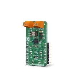
The output voltage can be selected by positioning the SMD jumper labeled as VOUT SEL to either 3V3 or 5V position. This jumper is used to select one of two resistor values for the FB pin of the ISL85403 IC. Values of these resistors are calculated so that the Click board™ offers a selection between 3.3V and 5V. Most embedded applications use one of these two voltages, so these values are selected accordingly. The output voltage presence is indicated by a LED indicator, labeled as OUT on the Click board™. This indicator is not driven by the ISL85403; instead, this LED is supplied with power directly from the output terminal.
Following the idea of providing a regulated 3.3V or 5V on the output, the Click board™ is equipped with the Power Good LED indicator. When there is an undervoltage or overvoltage condition, this pin will be asserted to a LOW logic level, allowing the red LED indicator labeled as UVP to turn ON. The undervoltage condition indicates that the voltage at the FB pin has dropped below 90% of the reference value, while the overvoltage condition indicates that the voltage at the FB pin has risen above 110% of the reference value, which is 0.8V for the ISL85403 IC. The status of the LED indicator can also be read by the host MCU since the PGOOD pin of the ISL85403 IC is also routed to the INT pin of the mikroBUS™.
The Buck-Boost 3 Click also features the EN pin, which is used to enable the ISL85403 IC. When there is a HIGH logic level on this pin, the buck-boost IC will be enabled. This pin is pulled to a HIGH logic level by an onboard resistor in case this pin is left floating. This pin is routed to the CS pin of the mikroBUS™, allowing the host MCU to control the Buck-Boost 3 Click.
Features & Specs
- Interface: GPIO
- Compatibility: mikroBUS™
- Dimensions: 42.9 x 25.4mm
- Input Voltage: 3.3V or 5V
Documentation
Customer Reviews
Stock and Customer Discounts
Available Discounts
- $33.20 | 25+ units
- $31.46 | 100+ units