
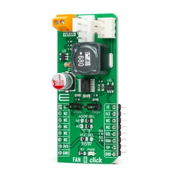
MIKROE Fan 4 Click
Fan 4 Click is a very compact, two-wire fan driver.
Product Overview
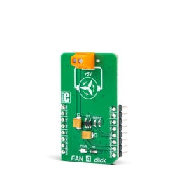
Fan 4 Click is a very compact, two-wire fan driver. It utilizes an integrated 5V, DC, brushless-motor driver chip. Its output voltage regulation and current limiting capabilities allow the speed control for the two-wire DC brushless motors. The Click board™ uses the LTC1695 IC, which features an integrated 6-bit DAC. The DAC regulates the output voltage in the range from 0 to 4.92V. This IC also has some additional features, such as the maximum output current limiting, and thermal shutdown protection. There is also a startup boost timer which ensures reliable startup of the fan, connected to the output terminal.
This Click board™ uses the I2C communication protocol, which is used to issue a command to the internal 6-bit DAC and set the output voltage. The fault status is also indicated on the I2C bus. The features such as a very compact size of the driver IC, a low number of external components needed, the high efficiency of the integrated PMOS regulator, the current limiting, and the shutdown protection, make Fan 4 Click an ideal solution for driving low-power 5V DC brushless motors, such as the ones used for cooling the computer power supplies and laptops, for spot cooling, some general purpose battery operated systems, and more. It can also be used whenever the programmable voltage regulation is required, providing up to 4.92 V and 180 mA to the connected load.
Fan 4 Click offers a programmable output voltage regulation, primarily aimed at controlling the speed of the 5V DC brushless fan drivers, which otherwise can't be controlled by the PWM signal, phase commutation or some other method, leaving only the option to be controlled by changing the power supply voltage. This Click board™ utilizes the LTC1695, an I2C fan speed controller, from Analog Devices. This controller IC uses a very compact SOT23 package case, requires a very low number of additional components, and it is really easy to be controlled by the two-wire I2C bus. This makes it a perfect solution for the fan speed regulator, that can be used for components cooling in various electronic designs. The speed control is very desirable in such applications, but the complexity associated with driving of some other, more advanced types of fan motors that offer speed regulation, often leads to using cheaper, two-wire 5V DC brushless fans, which do not offer any other means to control their speed but to reduce the power supply voltage.
Brushless motors can sometimes exhibit the stall effect if started with the reduced voltage. Although the fan will not rotate, the current will still be consumed, making the stall condition sensing difficult. Therefore, the LTC1695 driver features an internal boost timer, which can be activated by the user, via the I2C command. During the time-out period of the boost timer (250ms), the voltage at the output will be set at the maximum value (4.92V), so the reliable startup sequence of the fan motor is ensured. The LTC1695 datasheet offers some fan models that have been tested with this IC. If there is still a problem with the specific fan model, the firmware on the host MCU can always be utilized to apply a startup boost with an arbitrary interval.
The LTC1965 also features an undervoltage protection (UVLO). If the input voltage stays below 2.9V, the IC will not be enabled, preventing erratic behavior on the output. However, when used with the MikroElektronika development system, the power supply is taken from the regulated power supply unit of the development board.
The internal logic structure of the LTC1695 is also very simple. It only has one 8-bit register. When writing to this register, bits D0 to D5 are used to set the DAC output voltage, while the D6 bit is used to enable the boost timer. Bit D7 is disregarded. When reading out the data, this register reflects the status of the LTC1695 IC, bit D7 indicates overcurrent condition, while the bit D6 indicates thermal shutdown. The remaining six bits are disregarded. During the startup sequence, the internal DAC is set to 0, so there will be no voltage at the output.
The Click board™ has its I2C pins routed to the corresponding pins of the mikroBUS™, and it uses the power from the mikroBUS™ +5V power rail, as already mentioned. The mikroBUS™ is quite capable of supplying the LTC1965 with the maximum amount current it can draw (about 180 mA). The output 2-pole screw terminal allows an external load to be connected. Although the Click board™ is aimed towards driving brushless fan motors, it can also be used as the programmable low drop regulator (LDO), or it can be used as a LED driver.
Features & Specs
- Interface: I2C
- Compatibility: mikroBUS™
- Dimensions: 42.9 x 25.4m
- Input Voltage: 5V
- Output Voltage: Min. 0V, Max. 4.922V
- Output Current Limit: 180mA
Customer Reviews
Stock and Customer Discounts
Available Discounts
- $14.20 | 25+ units
- $13.46 | 100+ units