
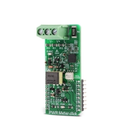
MIKROE PWR Meter Click
PWR Meter Click is a power measurement Click board™, capable of measuring voltage and current through the load, connected to either AC or DC power source.
Product Overview
PWR Meter Click is a power measurement Click board™, capable of measuring voltage and current through the load, connected to either AC or DC power source. PWR Meter Click uses the MCP39F511A, a very sophisticated monitoring IC from Microchip, with 16-bit processing core. It is used to calculate all the measurement parameters, returning values of multiple power parameters directly, over the UART interface, reducing the processing load on the host MCU. These parameters include active, reactive, and apparent power, current and voltage RMS, line frequency, and power factor.
NOTE: Do not apply higher voltage than 60V to this board! This Click is designed for lower voltage monitoring and evaluation of the MCP39F511A and its basic functionalities.
The measurement circuitry is completely isolated from the mikroBUS™, thus preventing any power surges from the measured circuit, which might cause damage to the low voltage components. Featuring very accurate power monitoring IC, with the accuracy of 0.1% across the 4000:1 dynamic range, this Click board™ is a perfect solution for various advanced measurement and monitoring purposes. Having in mind its processing core, and simplified command protocol over the UART interface, it can be driven even by slower, 8-bit MCUs, providing all the complex measurements which would have a large performance impact, otherwise. It can be used for the development of intelligent power distribution systems, real-time power characteristics measurement for AC or DC power supply units, power monitoring, and automation, or similar.
PWR Meter Click is based around the MCP39F511A, a power monitoring IC with on-chip 16-bit data processing and energy accumulation features, from Microchip. This IC is an advanced power monitoring IC, capable of calculating power characteristics, based on the measurements taken from the connected load and power supply. The IC is able to calculate active, reactive, and apparent power, current and voltage RMS, line frequency, and power factor. In addition, it features several useful functions, such as the programmable event reporting, with the onboard LED labeled as the EVENT.
PWR Meter Click uses the UART interface for the communication with the host MCU. The communication is based on the SSI (Simple Sensor Interface) protocol and it is fairly simple to use. This protocol is widely used for a point-to-point communication between the host MCU and other sensor devices, such as the MCP39F511A. The default rate of the protocol is 9600 bps, but it can be configured by the user. More information about the communication protocol itself and the commands that can be used can be found in the MCP39F511A datasheet. However, PWR Meter Click comes with a library which is compatible with all the MikroElektronika compilers. It contains functions which make working with the PWR Meter Click even simpler, saving a lot of development time.
The MCP39F511A incorporates two internal 24-bit Analog to Digital Converters (ADC), used to sample the voltage values on their differential inputs. One channel is used to measure the voltage drop across the shunt resistor with the value of 0.2Ω, while the second channel samples the voltage across the voltage divider on the input terminal. The voltage drop across the shunt resistor allows calculating the current through the connected load, while the voltage divider allows voltage measurement across the connected load, scaling it down so that it can be measured. A third, 10-bit ADC is used to measure the ambient temperature, needed for compensation. It is connected to an output of the MCP9700A, a low power linear active integrated thermistor, from Microchip.
The load should be connected to the 3-pole input terminal, between the input labeled with the L letter and the input labeled as the V-. The power supply should be also connected to the Click board™. Its hot (positive) end should be connected to the V+ labeled input of the 3-pole terminal, while the negative end should be connected to the input labeled as V-. The power supply should not exceed 50V. To better understand connection scheme, please take a look at the picture below.
The Click board™ features a complete galvanic isolation of the measured circuit. The power for the high voltage section is provided by the MCP1661, an efficient, integrated boost (step-up) DC/DC converter, from Microchip. The integrated boost converter is built using the flyback topology, allowing a complete galvanic isolation between the primary and secondary side, since it uses a transformer instead of a coil. The input voltage of the DC-DC converter is selected by an SMD jumper, labeled as the VCC SEL. The boosted voltage on the secondary of the transformer is further conditioned by the MCP17545, an LDO regulator from Microchip, and it is fixed to 3V. The output of the LDO is now galvanically isolated from the rest of the circuit, and it is used to supply the MCP39F511A monitoring IC and the additional thermal sensor with power.
Enabling or disabling the MCP1661 DC/DC converter controls the operation of the PWR Meter Click itself. The CS pin of the mikroBUS™ is routed to the EN pin of the MCP1661 converter, allowing the user to turn off the power for the monitoring IC. Setting the CS pin to a HIGH logic level will disable the converter, allowing current to sink through the transistor, thus setting the EN pin to a LOW logic level. Otherwise, the EN pin is pulled up to a HIGH level with the resistor, and the converter is enabled by default (when the CS pin of the mikroBUS™ is left floating, or driven to a LOW logic level) Galvanic isolation of the MCP39F511A data lines is done by using a bi-directional logic gate optocoupler, labeled as FOD8012A from ON Semiconductors. UART RX and TX lines from the MCP39F511A IC run through the integrated optocouplers and are also completely isolated from the low voltage circuitry. The previously mentioned VCC SEL jumper also selects the voltage for the optocoupler, allowing both 3.3V and 5V tolerant MCUs to be interfaced with the Click board™.
Features & Specs
- Interface: UART
- Compatibility: mikroBUS™
- Dimensions: 57.15 x 25.4mm
- Input Voltage: 3.3V or 5V
Documentation
Customer Reviews
Stock and Customer Discounts
Available Discounts
- $39.85 | 25+ units
- $37.76 | 100+ units