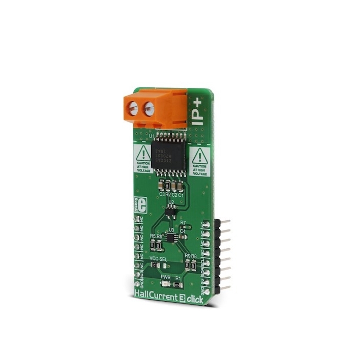
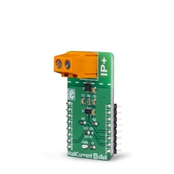
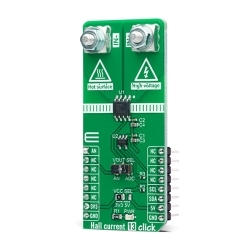
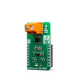
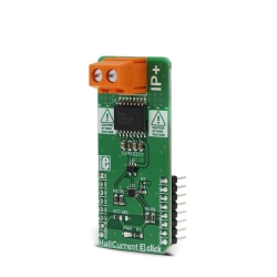
MIKROE Hall Current 3 Click
Hall current 3 Click utilizes the MLX91210, a linear Hall current sensor, from Melexis.
Product Overview
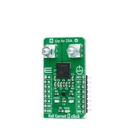
Hall Current 3 Click is a very accurate current measurement Click board™, which utilizes the Hall effect to provide a precise and reliable measurement of reasonably high current. Its most distinctive feature is a very low series resistance of only 0.7mΩ, making this device a nearly-perfect ammeter. The maximum current which can be measured by the MLX91210 integrated Hall sensor IC goes up to ±30A, but in respect to the nominal current measurement rating of the sensor, the current measurement is limited to about ±10A. The measurement is thermally compensated and conditioned by the high-speed integrated analog front-end sections of the Hall sensor IC. The current measurement value can be obtained from the onboard 12bit A/D converter, via the I2C interface.
Featuring a reasonably high current range that can be measured, extremely low series resistance, a differential current sensing by two integrated Hall plates, offering robustness and resistance towards external magnetic interferences, high isolation voltage of the IC itself, very low thermal drift, and fast response time with no hysteresis, this Click board™ can be used for a wide range of measuring and monitoring applications in audio applications, telecommunication applications, white goods applications, and basically in every application which requires reasonably high current measurement or monitoring.
Hall Current 3 Click utilizes the MLX91210, a linear Hall current sensor, from Melexis. This sensor utilizes the Hall effect phenomenon to measure the current passing through the input pins of the IC. This allows the series resistance to stay very low, in magnitudes of μΩ, reducing dissipation and losses in the main current flow. The main current flow through the input rails of the IC generates a magnetic field, which causes the Hall effect on two integrated Hall plates. These two plates are connected differentially, preventing foreign magnetic interferences to influence the measurement. A front-end section conditions and amplifies the signal, canceling out interferences. The conditioned signal is then available at the VOUT pin of the MLX91210, with a linear dependency of the input current. It is further routed to an A/D converter. The VOUT voltage is very stable and has a very low sensitivity drift over temperature (±1.5 % with nominal current).
The VOUT pin of the MLX91210 stays at 50% of VDD (5V), at 0A of current. This allows to measure both polarities: positive current polarity will pull the VOUT above half of the VDD, while negative current polarity will draw the VOUT pin below the VDD voltage. The MLX91210 also features fault reporting if overvoltage, undervoltage, or calibration data CRC error occurs. It will set the VOUT pin to a high impedance mode (Hi-Z). The datasheet offers an explanation about Hi-Z timings for each type of error. The resolution of the MLX91210 IC can be determined from the full IC label: MLX91210KDF-CAS-101-SP, where CAS-101 means that it has the analog voltage resolution of 80mV/A or ±25A for the full scale (FS) measurement.
The output voltage is also routed to the MCP3221, a 12 Bit SAR type ADC with the I2C interface, from Microchip. This ADC is used in several different Click board™ designs, as it yields accurate conversions, it requires a low count of external components, and has a reasonably good signal to noise ratio (SNR). It can achieve up to 22.3ksps, which allows good measurement resolution for the most purposes. After the VOUT measurement voltage has been converted to a digital value, it can be read via the I2C bus of the MCP3221 ADC.
Since the ADC IC works only with 3.3V communication voltage levels, the Click board™ is equipped with the PCA9306, a bi-directional I2C level translator. This IC accepts two voltage levels: one reference voltage for the input signal, and other reference voltage for the output signal. The output reference signal can be selected with the VCC SEL jumper, allowing communication with both 3.3V and 5V MCUs. The I2C bus already contains pull-up resistors included, so no further configuration is needed, it can be used right out of the box.
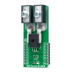
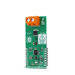
The input terminal has the cross section of 2.5mm, so it can accept a high input current, more than 10A. It has two input poles: IP+ and IP-. Conductors with the current that needs to be measured can be connected to this terminal.
Note: Since the MLX91210 provides up to 2.5 kV AC and 390 V DC, a special care should be taken if working with the high voltage. The Click board™ contains exposed areas which can be lethal if touched, while operated at high voltages.


Features & Specs
- Interface: I2C
- Compatibility: mikroBUS™
- Dimensions: 57.15 x 25.4mm
- Input Voltage: 3.3V or 5V
- Thermal Drift: Typ. ± 0.06A, Max. ± 0.12A
- Sensitivity: Min. 78.8mV/A, Typ. 80mV/A, Max. 81.2mV/A
- Nominal Sensor Range: ±10A
Documentation
Customer Reviews
Stock and Customer Discounts
Available Discounts
- $18.95 | 25+ units
- $17.96 | 100+ units