
MIKROE H-Bridge Click
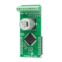
The Click board™ uses the MC34933, a dual H-bridge driver, from NXP.
Product Overview
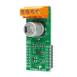
H-Bridge Click is a high-efficiency dual H-bridge driver Click board™, capable of providing reasonably high current while driving the connected load with up to 7V. Since the used driver IC has two full H-bridge channels, this Click board™ is an ideal solution for driving smaller bipolar stepper motors. H-Bridge Click provides driving in both directions, with an addition of the brake mode, and the high impedance mode (Hi-Z). Overshoot current suppression algorithm protects the output stages from being damaged if both high-side and low-side MOSFETs on a single H-bridge channel become conductive.
Four control input lines allow independent control of the two H-bridge channels via the MCU. Featuring a set of protection and driving functions, this highly efficient Click board™ can be used in a wide range of applications, where driving smaller bipolar step motors or small brushed DC motors is required. It is an ideal solution for light 3D printer elements driving, for precision actuators, an accurate positioning of various moving elements by using stepper motors, and similar applications.
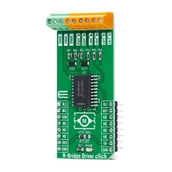
The Click board™ uses the MC34933, a dual H-bridge driver, from NXP. This IC is a highly integrated device, which requires a minimal number of external elements. Each of the H-bridge channels features two high-side and two low-side MOSFETs, used to control the current flow through the coils of the motor. The driver IC is produced by using the Freescale's proprietary SMARTMOS process, which ensures high efficiency and low power consumption. The total resistance across the output stage drivers is only 0.8Ω, allowing peak currents up to 1.5A, and 1A for the normal operation at 25˚C.
Driving H-bridge channels (and the connected load) is implemented by using four control input lines, two per channel. The truth table below illustrates how the control inputs affect the output stages. H-Bridge Click can be used to drive bipolar step motors in full step or half-step mode, offering full control over the motor driving functions. The H-Bridge Click can also be used for driving DC brushed motors. Special cases are when both control inputs of a single H-bridge channel are set to a HIGH or to a LOW logic state. In the first case, the output stage will be set to a high impedance (Hi-Z) mode. In the second case, both outputs of the H-bridge Click will be tied up to the GND, discharging the remaining coil current, performing so-called rheostatic (dynamic) braking. The Hi-Z mode is also activated as a protection measure when the temperature is too high, or when the power supply voltage drops under a certain threshold.
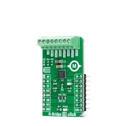
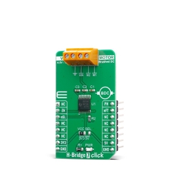
The control inputs are routed to the mikroBUS™ pins for an easy connection with the MCU. IN1A and IN1B control pins of the MC34933 driver IC, used to control the first H-bridge channel, are routed to the PWM and CS pins of the mikroBUS™ respectively, while the IN2A and IN2B control pins are routed to the AN and RST pins of the mikroBUS™. These pins are labeled as I1A, I2A, I1B, I2B, on the Click board™.
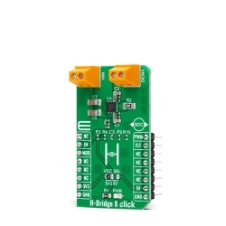
The power supply for the logic section of the IC is provided by the mikroBUS™ power rails. The ability of the driver IC to work with logic levels in the range of 3.3V to 5V simplifies the interfacing to MCUs that work with both voltages: it is enough to move the onboard SMD jumper labeled as VCC SEL, and select the desired logic voltage level between 3.3V and 5V.
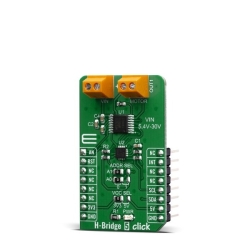
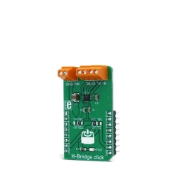
The motor coils are supplied with the power from either the external power supply, or by the mikroBUS™ power rail, selected with the VCC SEL jumper. When working with motors that consume more power than available at the mikroBUS™ power rail, it is advisable to connect the external power supply and move the jumper labeled as VIN SEL to the VIN position. By default, this jumper is set to use the mikroBUS™ power supply (VCC position). The external DC power supply can be connected to the two-pole input screw terminal, with its inputs labeled as GND and VIN. The stepper motor coils can be connected to the four-pole screw terminal, with its inputs labeled as 1A, 1B, 2A, 2B. These labels correspond to the H-bridge outputs from the driver IC itself: 1A is routed to the OUT1A, 1B to the OUT1B, and so on.
The Click board™ can be easily driven via the GPIO pins of the host MCU. However, MikroElektronika provides a library that contains functions compatible with the MikroElektronika compilers, which can be used for simplified control of the H-Bridge Click. Library offers functions for setting the rotation speed with selectable acceleration and deceleration, direction, half and full step driving mode, setting the output stages, and more. The library also contains an example application, which demonstrates the use of these functions. This example application can be used as a reference for custom designs.
Features & Specs
- Interface: GPIO
- Compatibility: mikroBUS™
- Dimensions: 42.9 x 25.4mm
- Input Voltage: 3.3V or 5V
- Voltage at the VIN terminal: Min. 2V, Typ. 3.3V, Max. 7V
- Maximum Load Current (at 25°C): 1A
- VCC Undervoltage Threshold: Min. 2.0V, Typ. 2.2V, Max. 2.4V
Documentation
Customer Reviews
Stock and Customer Discounts
Available Discounts
- $15.15 | 25+ units
- $14.36 | 100+ units