MIKROE Altitude 2 Click
Altitude 2 Click is a high-resolution barometric pressure sensor Click board™.
Product Overview
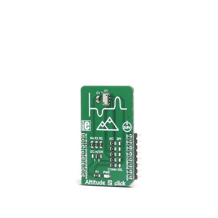
Altitude 2 Click is a high-resolution barometric pressure sensor Click board™. It provides very accurate measurements of temperature and atmospheric pressure, which can be used to calculate the altitude with a very high resolution of 20cm per step. Besides that, the device also includes features such as the ultra-low noise delta-sigma 24bit ADC, low power consumption, fast conversion times, pre-programmed unique compensation values, and more. Low count of external components requirement, along with the simple interface which requires no extensive configuration programming, makes this sensor very attractive for building altitude or air pressure measuring applications.
To measure the air pressure with a reasonable accuracy, the ambient temperature should also be taken into the consideration. The sensor component of the Altitude 2 Click provides an accurate ambient temperature measurement, which can be used to extract the compensated air pressure value from the readings. It can be set to work with both SPI and I2C communication protocol, by switching a few onboard jumpers. With its low power consumption, it is a great solution for using it in various mobile altimeter applications, such as the bike computers, variometers, data loggers, mobile altimeter and barometer stations, weather stations, and similar.
The barometric pressure sensor used on the Altitude 2 Click consists of a piezo-resistive sensor and the analog front end with the I2C/SPI interface. The sensor is manufactured using the advanced MEMS (Micro Electro Mechanical System) technology. It is optimized for a precise altitude measurement, based on the atmospheric pressure and temperature changes, in relation with altitude.
Each sensor IC is factory calibrated at two temperatures and pressures. The calibration coefficients are stored to its 128 bit PROM area. To calculate the correct values, these coefficients need to be used in the calculation, in order to derive real values from the raw, uncompensated readings, referred to as D1 and D2 in the datasheet of the device. These two raw values represent temperature and pressure measurements, converted by the internal 24bit delta-sigma ADC.
The compensation is needed because of several reasons. The barometric pressure measurement is influenced by a temperature and the offset value, measured at 0 Pa (zero offset coef.); the temperature measurement itself has a coefficient that differs from piece to piece; the altitude does not linearly depend on the barometric pressure, and so on. For this reason, the final altitude value needs to be calculated taking into account its compensating coefficients, referred to as C1-C6 in the datasheet.
The control of the Click board™ is very simple. After the power on, the device should be reset by sending the RESET command, making sure that the proper PROM data is loaded into the internal register. After this, the content of the PROM should be read by the host MCU, also by sending a command via the communication bus. Finally, a command to start the conversion of the uncompensated measurement can be sent to the Altitude 2 Click, which will respond with the conversion value, after the internal conversion period is finished. This will provide all the necessary information for the host MCU to extract the compensated values. More information about the commands and their responses can be found in the MS5607 datasheet.
However, MikroElektronika provides a library that contains functions compatible with the MikroElektronika compilers, which can be used for simplified programming of the Altitude 2 Click, such as the calculation function for the altitude measurement, based on the pressure and the temperature readings, raw values for the pressure and temperature, as well as the compensated (actual) pressure and temperature readings. The library also contains an example application, which demonstrates their use. This example application can be used as a reference for custom designs.
The Click board™ offers a choice between using the I2C and SPI communication protocol. When I2C communication protocol is selected, all jumpers labeled as the COMM SEL, should be set to the I2C position (left). When SPI is selected, all these jumpers should be moved to the SPI position (right). When I2C protocol is selected, another onboard SMD jumper is used to set the LSB bit of the peripheral I2C address. Please note that when selecting I2C or SPI protocol, all of the COMM SEL SMD jumpers should be set at the same position (all to SPI, or all to I2C). Mixed position settings can result in the unresponsiveness of the Click board™.
There are no additional pins routed from the sensor IC, other than the lines used for the communication: SPI lines, labeled as SDI, SDO, SCK, and CS, and I2C lines, labeled as SDA and SCL. These lines are routed to the appropriate mikroBUS™ pins, used for I2C and SPI communication. The I2C lines, along with the CS line are pulled to a HIGH logic level by the onboard resistors. Please note that the Click board™ supports only 3.3V MCUs and it is not intended to be connected or controlled via the 5V MCU without a proper level shifting circuitry.


Features & Specs
- Interface: I2C, SPI
- Compatibility: mikroBUS™
- Dimensions: 42.9 x 25.4mm
- Input Voltage: 3.3V
- Pressure Range: Min 10 mbar, Max. 1200 mbar
- Pressure Measurement Resolution: Min. 0.13Pa, Max. 0.024Pa
- Response Time: Min. 0.5ms, Max. 8.22ms
- Temperature Range: Min. -40˚C, Max. +85˚C
- Temperature Accuracy: Min. -0.8˚C, Max. +0.8˚C
Documentation
Customer Reviews
Stock and Customer Discounts
Available Discounts
- $14.20 | 25+ units
- $13.46 | 100+ units