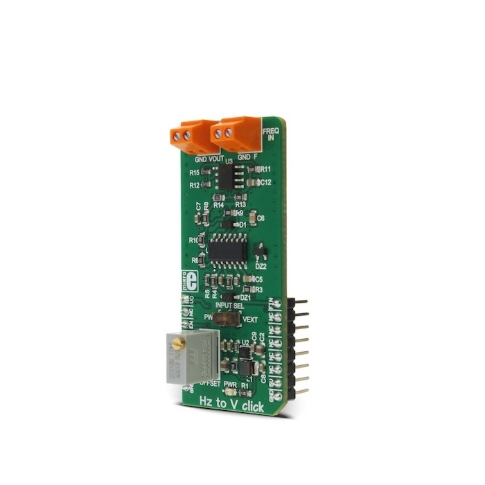
MIKROE HZ to V Click
The main component of the Hz to V Click is the TC9400, a voltage-to-frequency and frequency-to-voltage converter from Microchip.
Product Overview
HZ to V Click is a device that can converts input frequency of the signal with virtually any wave shape to a DC voltage output, with a level proportional to the input frequency. It has a linear response, and by applying a signal with the frequency between 1kHz to 10kHz on its input, the Click board™ will generate a DC voltage, ranging from 0.33V to 3.3V. Hz to V Click features very good linearity, covers a wide input frequency range from 1kHz to 10kHz and it has good temperature stability.
These features allow HZ to V Click to be used in various frequency to voltage applications: in instrumentation, industrial, and automation markets. It is well suited for use in AD conversion, long-term integration, frequency to voltage conversion, RPM measurement, capacitance measurement, frequency demodulation and similar applications which can benefit from an accurate and reliable frequency to voltage conversion.
The main component of the Hz to V Click is the TC9400, a voltage-to-frequency and frequency-to-voltage converter from Microchip. It accepts a signal with the frequency within a range between 1kHz and 10kHz on the input and generates DC voltage with the level corresponding to the input frequency, ranging from 0.33V to 3.3V, with a highly linear response. This signal is further passed through the operational amplifier, in order to scale it down to a level acceptable by the MCU. The input signal can be applied either to the PWM pin of the mikroBUS™ or the external input terminal. The input source can be selected with the onboard switch, labeled as INPUT SEL.
When Hz to V Click is operated for the first time, it needs to be calibrated. The Click is equipped with a variable resistor for the offset fine tuning. The following procedure should be followed to calibrate the device:
- An input signal with a frequency of 1kHz should be applied to the input. The offset should be adjusted so that a 330mV DC signal appears on the output.
HZ to V Click is equipped with the input signal terminal (FREQ IN), which is used to connect the signal with a frequency which is in the acceptable range between 1kHz and 10kHz. Besides this signal input terminal, it is possible to select the PWM signal generated by the host MCU as the input, too. INPUT SEL switch can be set so that the PWM pin from the mikroBUS™ is used as the control voltage input. It is recommended that the signal amplitude does not exceed 3.3V.
The output terminal (VOLT OUT) is used to output the generated voltage. As already explained, the voltage level depends on the input signal frequency. This generated voltage is also available on the AN pin of the mikroBUS™. The output signal is passed through the operational amplifier (OPAMP) which is used both as the output buffer and a voltage adjust stage for the output voltage. A well known general purpose operational amplifier LM318 from Texas Instruments is used for this purpose.
To provide 12V for the TC9400 and the LM318 OPAMP, Hz to V Click employs a boost converter built around the MIC2606, a boost regulator from Microchip, which works at 2MHz. This IC provides 12V for supplying the TC9400 out of 5V routed from the mikroBUS™ socket. The EN pin of the boost regulator is routed to the mikroBUS™ CS pin and it is used to enable power output from the boost regulator, effectively enabling the TC9400 itself. The EN pin is pulled to a HIGH logic level (3.3V) by the onboard resistor.


Features & Specs
- Interface: GPIO
- Compatibility: mikroBUS™
- Dimensions: 57.15 x 25.4mm
- Input Voltage: 3.3V, 5V
- Input Signal Amplitude: 3.3V
- Input Frequency: Min. 1,000Hz, Max. 10,000Hz
- Output Voltage Level: Min. 0.33V, Max. 3.3V
Documentation
Customer Reviews

Stock and Customer Discounts
Available Discounts
- $25.60 | 25+ units
- $24.26 | 100+ units