MIKROE RS232 2 Click
RS232 2 Click performs full RS232 to UART signal conversion, allowing both 3.3V and 5V operation.
Product Overview
The RS232 communication standard is established back in the ‘60s, but thanks to its implementation on a wide range of devices - including PC motherboards, it gained a lot of popularity and it is still in use. Over time, this standard went through many revisions and the most recent revision is TIA-232-F (R2012). Although it was originally developed to connect teletypewriters and modems, nowadays it is used for serial communication between a wide array of different devices.
To implement the RS232 communication standard on the MCUs, it is necessary to convert the voltage levels to the levels acceptable for the modern MCUs. RS232 2 Click performs full RS232 to UART signal conversion, allowing both 3.3V and 5V operation. Additionally, it features ±15 kV ESD protection for the RS-232 I/O pins. These attributes make this Click a perfect solution for battery powered, hand-held and portable equipment, PDAs, palmtops, digital cameras, and other devices that still support the RS232 standard.
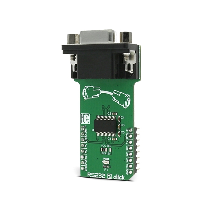
The integrated circuit used to provide an electrical interface between RS232 and UART on the RS232 2 Click is the MAX3237E, a 3V to 5.5V multichannel RS232, 1 Mbit/s line driver/receiver from Texas Instruments. This device allows communication at 1 Mbit/s and allows 5V logic levels, even when working with 3.3V power supply. However, there is an onboard SMD jumper that allows selection of power supply voltage between 3.3V and 5V, if there is a requirement.
The MAX3237E IC consists of five line drivers, three line receivers, and a dual charge pump circuit with ±15 kV pin to pin ESD protection for the serial port I/O pins. Those charge pumps along with the external capacitors, allow the device to run from a single 3V to 5.5V supply, providing the required RS232 voltage levels, which can go up to ±15 V as per standard. The MAX3237E IC generates an RS232 voltage in the range of ±13 V and accepts RS232 signal levels in the range of ±25 V.
To provide the minimal functionality of the UART interface, at least three data lines have to be used: RX line, routed to the mikroBUS™ RX pin (on the Click board™ side), TX line, routed to the mikroBUS™ TX pin (on the Click board™ side), and the GND. Otherwise, this device supports the full stack of RS232 control lines, excluding the Data Set Ready line (DSR). Other relevant RS232 bus lines routed to the mikroBUS™ pins are: Data Terminal Ready (DTR) - routed to the AN pin, Data Carrier Detect (DCD) - routed to the RST pin, Clear To Send (CTS) - routed to the CS pin, Ring Indicator (RI) - routed to the PWM pin, Request To Send (RTS) - routed to the INT pin. All these lines, are actually control lines and are used optionally by the RS232 device.
RS232 2 Click features the standardized DE-9 connector for easy connection to the RS232 device. By switching the VCC SEL jumper, it is possible to select the power supply voltage for the RS232 2 Click. Although it can work with 5V, the device will accept UART signals of 5V even while working in 3.3V mode.


Features & Specs
- Interface: GPIO, UART
- Compatibility: mikroBUS™
- Dimensions: 57.15 x 25.4mm
- Input Voltage: 3.3V or 5V
- Input Voltage Range on RS232: Min. -25V, Max. +25V
- Output Voltage Range on RS232: Min. -13V, Max. +13V
- Data Rate: Min. 250 kbps, Max. 1000 kbps
Documentation
Customer Reviews
