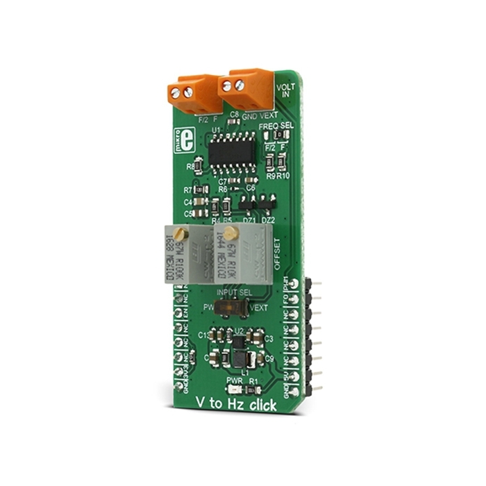
MIKROE V to Hz Click
V to HZ Click is a device that converts an analog voltage input signal into a pulse wave signal of a certain frequency.
Product Overview
V to HZ Click is a device that converts an analog voltage input signal into a pulse wave signal of a certain frequency. It has a linear response, so applying a voltage in a range of 0 to 5V on its input, will result in generating the pulse train with frequency linearly proportional to the input voltage. This Click features very good linearity, covers a frequency range from 10Hz to 10 kHz and it has a good temperature stability.
These features allow this device to be used in various voltage to frequency applications: it can be used in various applications in instrumentation, industrial, and automation markets. It is well suited for use in AD conversion, long-term integration, linear frequency modulation, voltage-to-frequency conversion and it can be used as the variable clock signal generator.
The main component of the V to HZ Click is the TC9400, a voltage-to-frequency and frequency-to-voltage converter from Microchip. It accepts voltage at its input and generates a pulse train, with a frequency linearly proportional to the input voltage. The pulse train is present on two output pins: the full frequency pin outputs signal with the pulse rate linear to the input voltage, while the half frequency pin outputs signal with the pulse rate equal to the half of the full frequency pin pulse rate.
When V to Hz Click is operated for the first time, it needs to be calibrated. The Click is equipped with two variable resistors for gain and offset fine tuning. There are several steps that should be followed when calibrating:
- An input signal of 10mV should be applied to the input. The offset should be adjusted so that a 10Hz signal appears on the output
- An input signal of 5V should be applied to the input. The gain should be adjusted so that 10kHz signal appears on the output
V to HZ Click is equipped with the input voltage terminal (VOLT IN), which is used to connect the control voltage up to 5V. Besides having control voltage input on this terminal, it is possible to select the voltage generated by the MCU as the control voltage input, too. INPUT SEL switch can be set so that the PWM pin from the mikroBUS™ is used as the control voltage input. The PWM signal generated by the MCU is filtered out by the onboard low pass filter so that the control voltage remains constant. For this reason, PWM signal frequency from the MCU should be at least 40 kHz.
The output terminal (FREQ OUT) is used to output the generated frequency. There are two outputs routed to this two-pole screw terminal: the first output is full frequency output (f), while the second output is the half of the generated frequency (f/2). The frequency output is also routed to the INT pin of the mikroBUS™. To select between the half and the full frequency output routed to the INT pin, the FREQ SEL SMD jumper needs to be switched to the correct position. Both of the half frequency and the full frequency outputs are pulled HIGH (3.3V) with an onboard resistor, which means that the output generated signal amplitude will be 3.3V.
To provide 12V for the TC9400, V to Hz Click employs a boost converter, built around the MIC2606, a boost regulator from Microchip, which works at 2MHz. This IC provides 12V for supplying the TC9400 out of 5V routed from the mikroBUS™ socket. EN pin of the boost regulator is routed to the mikroBUS™ CS pin and it is used to enable power output from the boost regulator, effectively enabling the TC9400 itself. EN pin is pulled to a HIGH logic level (3.3V) by the onboard resistor.


Features & Specs
- Interface: GPIO
- Compatibility: mikroBUS™
- Dimensions: 57.15 x 25.4mm
- Input Voltage: 3.3V, 5V
- Output Frequency: Min. 10Hz, Max. 10,000Hz
- Output Signal Amplitude: 3.3V
Documentation
Customer Reviews
